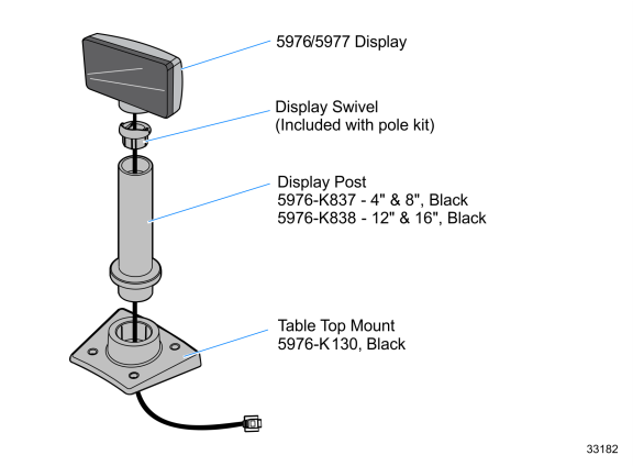
5976–K837/K838 Customer Display Post Mount
This kit provides the components to mount NCR 5976/5977 Customer Display in a remote table–top mount.
There are two versions of this kit:
•5976–K837 — 4ʺ and 8ʺ posts, Black
•5976–K838 — 12ʺ and 16ʺ posts, Black
Note: A Remote Table Top/Counter Top Mount (5976–K130, Black) is also required for remote configurations.
Note: For kits in G11 and in CG1 colors, refer to 597x Customer Display Post Mount Kit Instructions (5975–K833–836) for more information.
Installation Procedures
NCR 5976 Customer Displays
Note: This document discusses how to install a Remote Table–Top mount. For integrated configuration see your terminal User Guide for installation procedures.
1.Locate the Display Mount within 4 meters (13 ft.) of the host terminal.
2.Determine if the cable should be routed down through the mounting surface or if it should be run on top of the surface. Drill a hole if necessary.
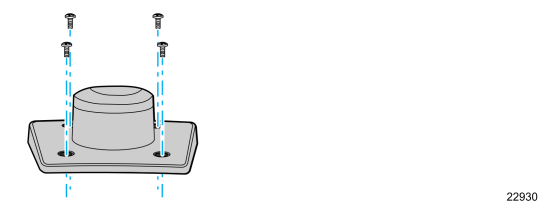
3.If you are installing with a post greater than 215 mm (8.5 in.), secure the Base Plate with screws that are provided.
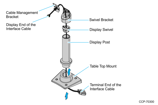
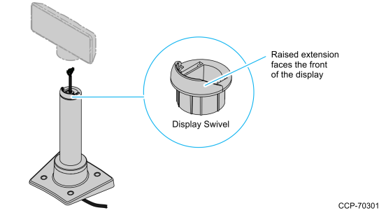
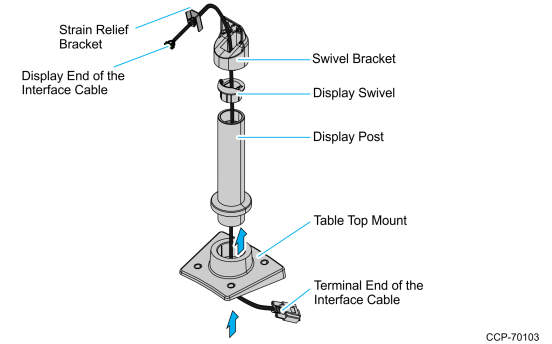
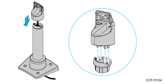
4.Route the display end of the Interface Cable through the Table–Top Mount, the Display Post, and the Display Swivel.
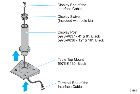
5.Assemble the post components.
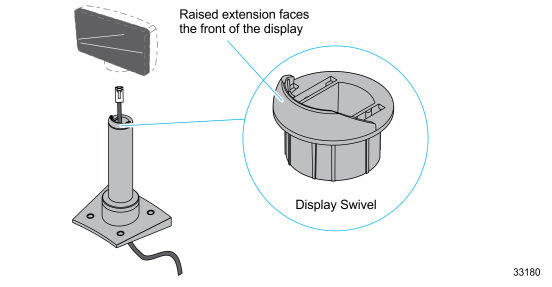
Note: The raised extension of the Display Swivel is facing the front of the unit, which permits the Display to be tilted towards the back.
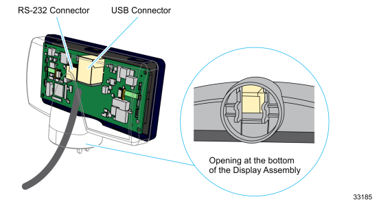
6.Connect the Interface Cable to the Display Module by inserting the Interface Cable through the opening at the bottom of the Display Assembly and to the designated connector on the Display Module.
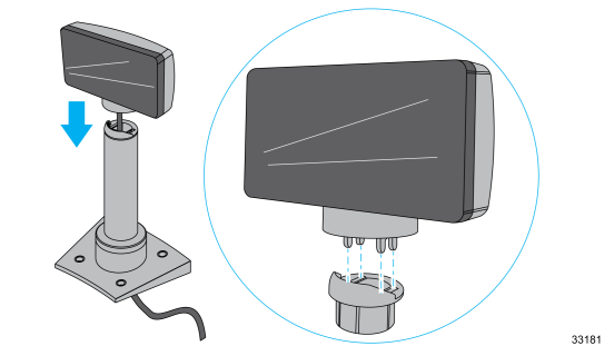
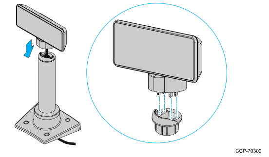
7.Connect the display to the post assembly.
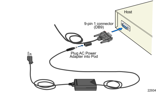
8.Connect the terminal end of the Display Cable to the host terminal.
•RS–232 Interface (Powered)
Connect the I/F cable to a powered RS–232 connector on the terminal.
•RS–232 Interface (Non–Powered)
Connect the I/F cable to a non–powered RS–232 connector on the terminal. Connect a Power Brick to the I/F cable and an AC outlet.
Configure the terminal serial port as follows:
9600 baud, 8 data bits, 1 start bit, 1 stop bit, No parity
•USB Interface (Powered)
Connect the I/F cable to a powered 12V USB + Power connector on the terminal.
•USB Interface (Non–Powered)
Connect the I/F cable to a non–powered USB connector on the terminal. Connect a Power Brick to the I/F cable and an AC outlet.
NCR 5977 Customer Displays
1.Locate the Display Mount within 4 meters (13 ft.) of the host terminal.
2.Determine if the cable should be routed down through the mounting surface or if it should be run on top of the surface. Drill a hole if necessary.
3.If you are installing with a post greater than 215 mm (8.5 in.), secure the Base Plate with screws (4) that are appropriate for the mounting surface.
4.Install the Post Mount, the Display Assembly, and the Interface Cable. Follow the procedures that correspond to the type of cable bracket used.
•For Cable Management Bracket, refer to Using Cable Management Bracket.
•For Strain Relief Bracket, refer to Using Strain Relief Bracket.
Using Cable Management Bracket
1.Route the display end of the Interface Cable through the Table–Top Mount, the Display Post, the Display Swivel, the Swivel Bracket, and the Cable Management Bracket.
2.Assemble the post components.
Note: The raised extension of the Display Swivel is facing the front of the unit, which permits the Display to be tilted towards the back.
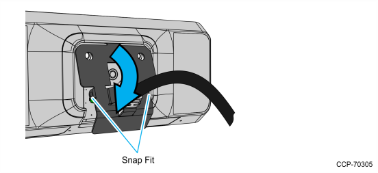
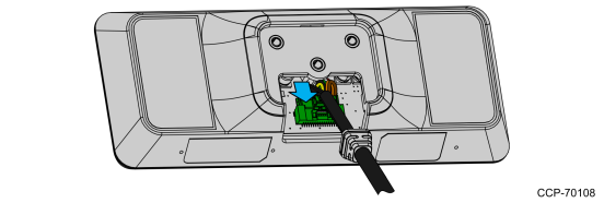
3.Connect the Interface Cable to the Display Module connector until the latch is engaged. Ensure that the latch is properly engaged by gently tugging on the cable.
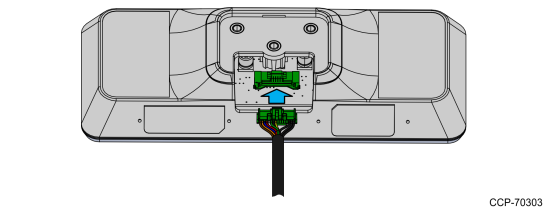
4.Slide the grooves of the Cable Overmold onto the tabs of the Cable Management Bracket.
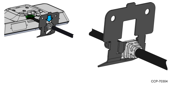
5.Route the excess cable to the right and around the board connector and install the Cable Management Bracket. Insert the tab of the Cable Management Bracket into the slot in the Rear Cover. Pivot the bracket as shown until it snaps into position.
Note: Ensure that the cables are not pinched when installing the bracket.
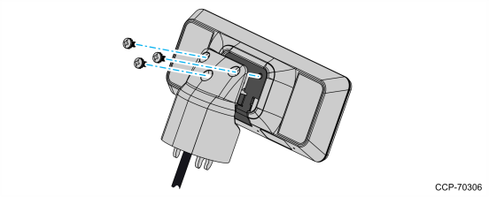
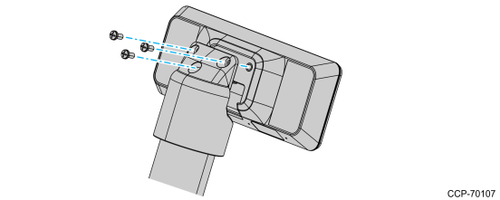
6.Install the Swivel Bracket by using the three M4x8 screws.
7.Connect the display to the post assembly.
8.Connect the terminal end of the Display Cable to the host terminal.
•RS–232 Interface (Powered)
Connect the I/F cable to a powered RS–232 connector on the terminal.
Configure the terminal serial port as follows:
9600 baud, 8 data bits, 1 start bit, 1 stop bit, No parity
•USB Interface (Powered)
Connect the I/F cable to a powered 12V USB + Power connector on the terminal.
•USB Interface (Non–Powered)
Connect the I/F cable to a non–powered USB connector on the terminal. Connect a Power Brick to the I/F cable and an AC outlet.
Using Strain Relief Bracket
1.Route the display end of the Interface Cable through the Table–Top Mount, the Display Post, the Display Swivel, and the Swivel Bracket.
Note: The Strain Relief Bracket may be installed later.
2.Assemble the post components.
Note: The raised extension of the Display Swivel is facing the front of the unit, which permits the Display to be tilted towards the back.
3.Attach the Swivel Bracket to the Display Swivel.
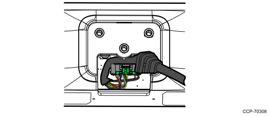
4.Connect the Interface Cable to the Display Module connector until the latch is engaged. Ensure that the latch is properly engaged by gently tugging on the cable.
5977–1000
5977–2000
5.Attach the Strain Relief Bracket.
a.Attach the Strain Relief Bracket to the cable, right below the Cable Overmold.
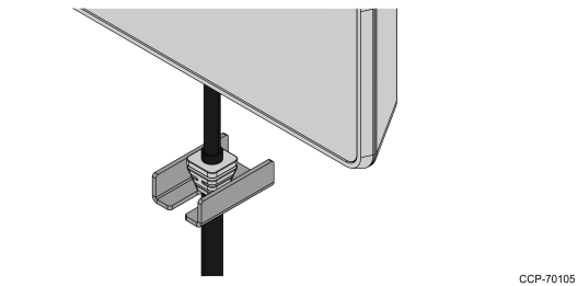
b.Carefully pull the cable down so the Strain Relief Bracket fits in the middle of the Swivel Bracket and rests on top of the Display Swivel.
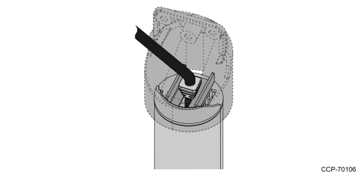
6.Attach the display to the Swivel Bracket by using the three M4x8 screws.
Note: Ensure that no cables are pinched.
7.Connect the terminal end of the Display Cable to the host terminal.
•RS–232 Interface (Powered)
Connect the I/F cable to a powered RS–232 connector on the terminal.
Configure the terminal serial port as follows:
9600 baud, 8 data bits, 1 start bit, 1 stop bit, No parity
•USB Interface (Powered)
Connect the I/F cable to a powered 12V USB + Power connector on the terminal.
•USB Interface (Non–Powered)
Connect the I/F cable to a non–powered USB connector on the terminal. Connect a Power Brick to the I/F cable and an AC outlet.