P1535 POS Stand
Introduction
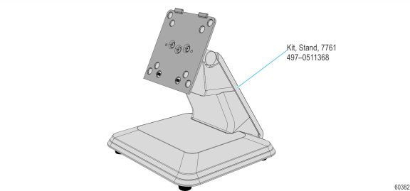
This kit provides a P1535 POS (7761) Table Top Stand.
Kit Content
Installation Procedure
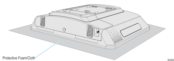
1.Lay the terminal face down on a flat surface.
Caution: Always use a soft material (cloth, foam) to protect the display screen when placing the terminal face down.
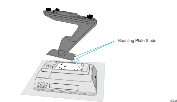
2.Insert the Mounting Plate Tabs (2) into the openings in the Rear Cover at a slight angle as shown.
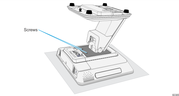
3.Rotate the stand flush into the Rear Cover and secure it with the mounting screws (2).
Installing the Power Supply
The P1535 terminal receives power from an external 19 V or 24 V power supply.
Caution: The P1535 terminal requires the NCR 19 V or 24 V power supply that is shipped with the terminal. Use of other power supply may cause damage to the unit. Do not connect or disconnect the 19 V or 24 V Power Cable from the terminal with the AC Power Cord still connected to an AC outlet.
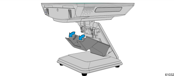
1.Pivot the display toward the back.

2.Remove the Upper Stand Cover by pivoting it away from the stand. The cover has a simple snap fit connection at the top.
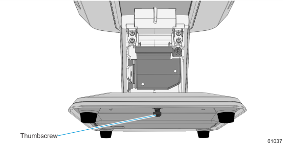
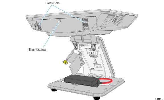
3.Loosen the Thumbscrew that secures the Base Cover.
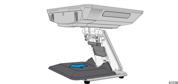
4.Slide the Base Cover toward the front slightly to disengage it from the Base.
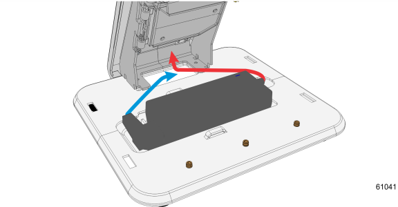
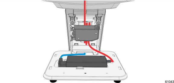
5.Route the AC Power Cord up through the base of the stand.
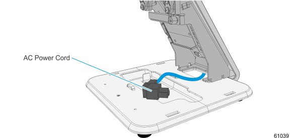
6.Attach the Power Cord to the Power Brick.
7.Install the Power Brick in the Base.
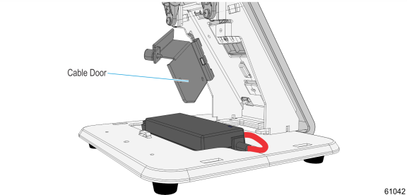
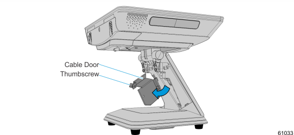
8.Loosen the thumbscrew to open the Cable Door.
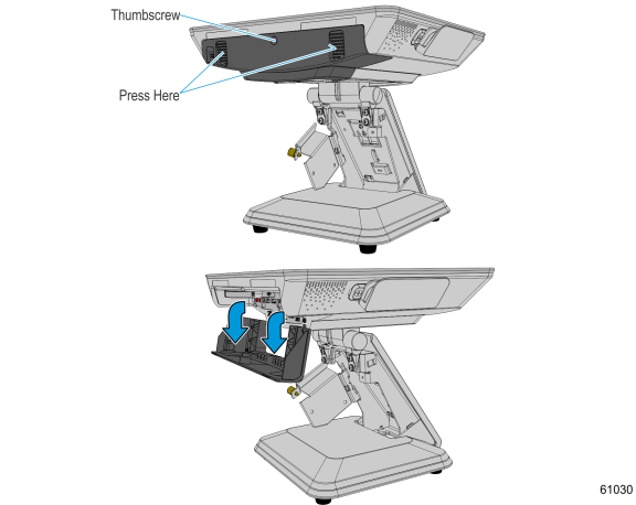
9.Loosen the screw on the Terminal Cable Cover. To open, press the indentations on the Cable Cover to unlatch the cover then pivot to open.
10.Route the power cable up through the stand and connect the power supply cable to the Power In connector.
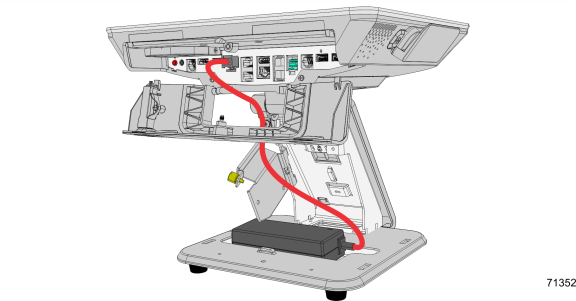
11.Secure the excess power cables with a cable tie and place the cables behind the Cable Door.
12.Close the Cable Door and tighten the thumbscrew to secure the door.
13.Reinstall the Base Cover and tighten thumbscrew to secure cover.
14.Connect the AC Power cord to an AC outlet.
Cable Routing
1.Pivot the display toward the back.
2.Remove the Upper Stand Cover by pivoting it away from the stand. The cover has a simple snap fit connection at the top.
3.Open the Cable Door (Thumbscrew).
4.Loosen the screw on the Terminal Cable Cover. To open, press down on the indentations in the Cable Cover to unlatch the cover and then pivot the cover open.
Note: Ensure that the screw is disengaged from the threads.
5.Route the cables up through the stand and out of the Terminal Cable Cover.
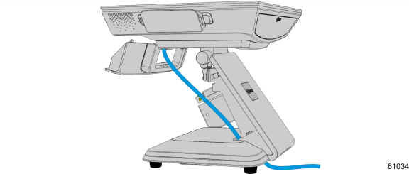
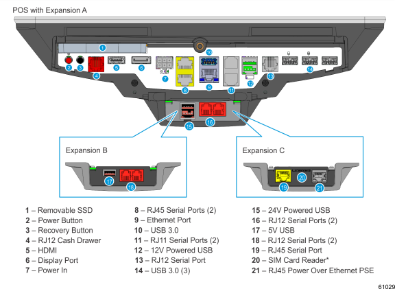
6.Connect the peripheral cables to the I/O Panel.
Note: SIM cards must be inserted while the terminal is powered off.
7.Install the Terminal Cable Cover and tighten thumbscrew to secure cover.
8.Close the Cable Door and tighten thumbscrew to secure cable door.
9.Install the Upper Stand Cover.