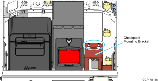
1.Install the Checkpoint mounting bracket on the right inner side of the lower module and secure it with the two hex nuts.
2.Install the Checkpoint Power Supply.
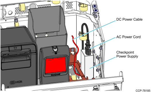
a.Route the DC Power Cable of the power supply through the bottom access hole of the mounting bracket.
b.Position the power supply on the right side of the mounting bracket.
c.Connect the AC Power Cord to the power supply.
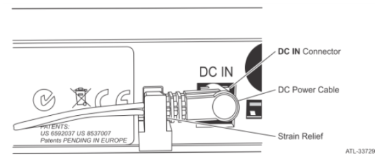
3.Connect the DC Power Cable to the DC In connector at the bottom of the Checkpoint Controller and slide the jack behind the Strain Relief.
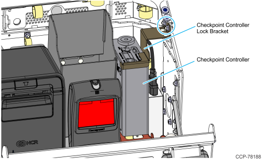
4.Install the Checkpoint Controller.
a.Route the Checkpoint Signal Cable through the bottom access hole of the mounting bracket and partially route it through the p-loops beside the Checkpoint Power Supply.
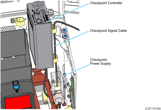
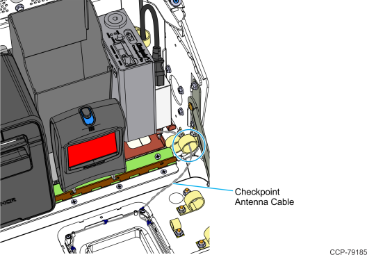
b.Position the Checkpoint Antenna Cable onto the cable slot on the mounting bracket, and place the Checkpoint Controller on the mounting bracket.
Caution: Ensure that no cables are pinched.
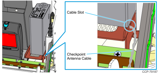
c.Route the Checkpoint Antenna Cable through the p-loop indicated in the image, and then tuck the excess cable length under the Checkpoint Controller mounting bracket.
d.Using a cable tie, bundle any excess length of the DC Power Cable. Place the bundle underneath the Checkpoint Controller mounting bracket.
e.Install the Checkpoint lock bracket on the right inner side of the lower module and secure it with the two hex nuts.
5.Connect the Checkpoint Signal Cable connector to the CKPT connector on the I/O Adapter. Secure it with p-loops along its route.
