5975–K833-K836 Customer Display Post Mount
Introduction
This kit provides the components to mount NCR 5972, NCR 5975, and NCR 5976 Customer Displays in an integrated configuration or a remote table–top mount.
There are six versions of this kit:
•5975–K833 — 4" and 8" posts, G11
•5975–K834 — 4" and 8" posts, CG1
•5976–K837 — 4" and 8" posts, BK
•5975–K835 — 12" and 16" posts, G11
•5975–K836 — 12" and 16" posts, CG1
•5976–K838 — 12" and 16" posts, BK
Note: A Remote Table Top/Counter Top Mount (5975–K910, G11 or 5975–K912, CG1) is also required for remote configurations.
Note: For kits in Black color, refer to 5976 Customer Display Post Mount Kit Instructions (5976–K837–838) for more information.
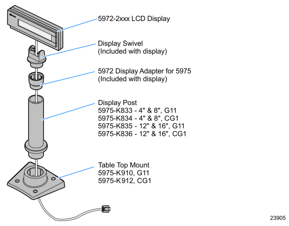
5972 Customer Display Assembly
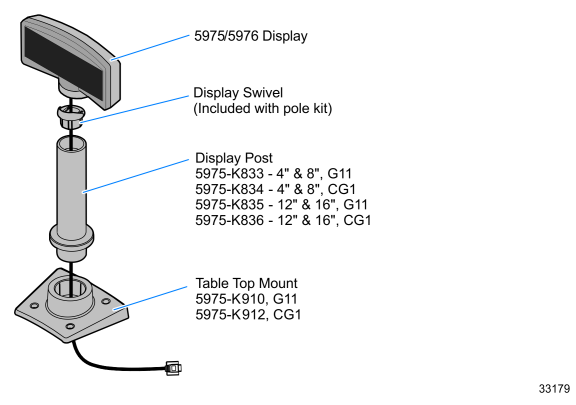
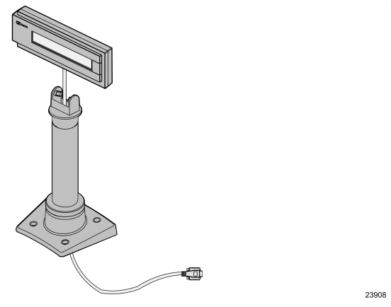
5975/5976 Customer Display Assembly
Installation Procedures
Note: This document discusses how to install a Remove Table–Top mount. For integrated configuration see your terminal User Guide for installation procedures.
NCR 5972 Customer Displays
1.Locate the Display Mount within 4 meters (13 ft.) of the host terminal.
2.Determine if the cable should be routed down through the mounting surface or if it should be run on top of the surface. Drill a hole if necessary.
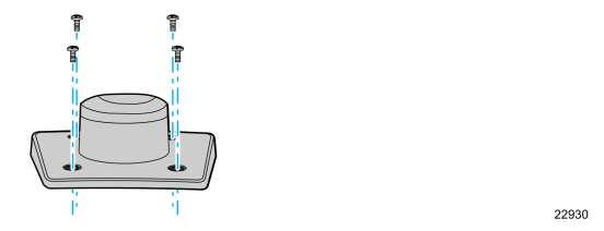
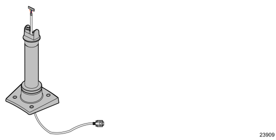
3.If you are installing with a post greater than 215 mm (8.5 in.), secure the Base Plate with screws that are provided.
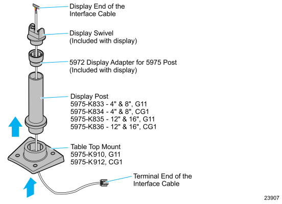
4.Route the display end of the Interface Cable through the Table–Top Mount, the Display Post, the 5972 Display Adapter, and the Display Swivel.
Note: The terminal end of the Interface Cable is too large to fit down through the post.
5.Assemble the post components.
6.Connect the Interface Cable to the Display Module.
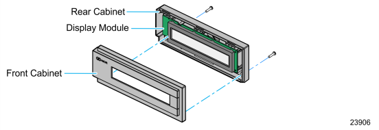
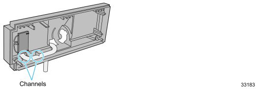
a.Remove the screws (2) from the rear cabinet and then remove the Front Cabinet.
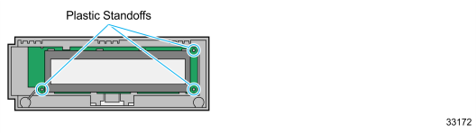
b.Remove the Display Module from the Rear Cabinet plastic standoffs (3).
c.Route the Interface Cable through the opening at the bottom of the Rear Cabinet and connect it to the Display Module.
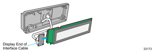
d.Reassemble the Display Assembly and secure the cabinet with the two screws.
Note: The cable is routed through the channels in the Rear Cabinet.
7.Connect the display to the post assembly.
8.Connect the terminal end of the Display Cable to an RS–232 connector on the host terminal.
NCR 5975/5976 Customer Displays
1.Locate the Display Mount within 4 meters (13 ft.) of the host terminal.
2.Determine if the cable should be routed down through the mounting surface or if it should be run on top of the surface. Drill a hole if necessary.
3.If you are installing with a post greater than 215 mm (8.5 in.), secure the Base Plate with screws (4) that are appropriate for the mounting surface.
4.Route the display end of the Interface Cable through the Table–Top Mount, the Display Post, and the Display Swivel.
Note: The terminal end of the Interface Cable is too large to fit down through the post.
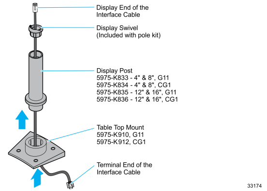
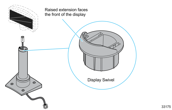
5.Assemble the post components.
Note: The raised extension of the Display Swivel is oriented toward the front of the unit, which permits the Display to be tilted to the rear.
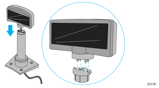
6.Connect the Interface Cable to the Display Module by doing any of the following:
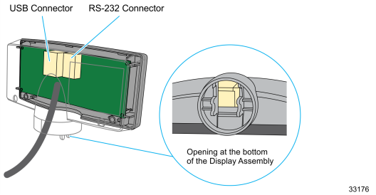
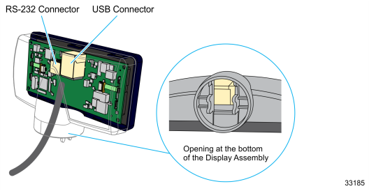
•Insert the Interface Cable through the opening at the bottom of the Display Assembly and to the designated connector on the Display Module.
Note: This is applicable to both 5975 and 5976.
•5975 Connectors
•5976 Connectors
•Disassemble the Display Assembly, and then connect the Interface Cable.
Note: This is applicable to 5975 only.
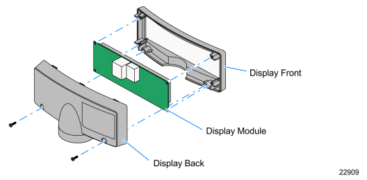
a.Remove the screws (2) from the Display Back.
b.Remove the Display Back.
c.Route the Interface Cable though the opening at the bottom of the Display Back and connect it to the designated connector on the Display Module.
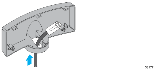
d.Reassemble the Display Assembly and secure the cabinet with the two screws.
7.Connect the display to the post assembly
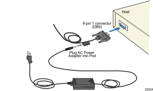
8.Connect the terminal end of the Display Cable to the host terminal.
•RS–232 Interface (Powered)
Connect the I/F cable to a powered RS–232 connector on the terminal.
•RS–232 Interface (Non–Powered)
Connect the I/F cable to a non–powered RS–232 connector on the terminal. Connect a Power Brick to the I/F cable and an AC outlet.
Configure the terminal serial port as follows:
9600 baud, 8 data bits, 1 start bit, 1 stop bit, No parity
•USB Interface (Powered)
Connect the I/F cable to a powered 12V USB + Power connector on the terminal.
•USB Interface (Non–Powered)
Connect the I/F cable to a non–powered USB connector on the terminal. Connect a Power Brick to the I/F cable and an AC outlet.