5976–K902/K903 Pole Assembly with Integration Tray Mount
Introduction
This kit provides the components to mount NCR 5976 Customer Display in an integration tray mount.
Kit Contents
The following tables show the two versions of this kit.
|
5976–K902 — 5976 Pole Assembly with Integration Tray Mount, Beige |
||
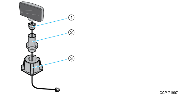
| 1 | 497-0440927 | 5975 Customer Display Swivel Mount, G11 |
| 2 | 497-0440769 | 5975 Customer Display Integration Pole, 4 Inch, G11 |
| 3 | 497-0427331 | Customer Display Post, G11, 7606 |
|
5976–K903 — 5976 Pole Assembly with Integration Tray Mount, Black |
||
| 1 | 497-0440929 | 5975 Customer Display Swivel Mount, Blk7 |
| 2 | 497-0440777 | 5975 Customer Display Integration Pole, 4 Inch, Blk7 |
| 3 | 497-0427333 | Customer Display Post, BLK7, 7606 |
Tools Required
The following tool is required to install this kit:
•#2 Phillips Screwdriver
Note: It is highly recommended to use magnetized screwdrivers to easily handle the screws.
Installation Procedures
1.Locate the Display Mount within 4 meters (13 ft.) of the host terminal.
2.Determine if the cable should be routed down through the mounting surface or if it should be run on top of the surface. Drill a hole if necessary.
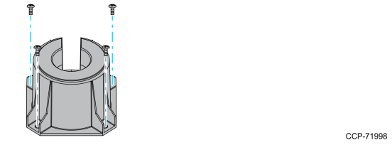
3.If you are installing with a post greater than 215 mm (8.5 in.), secure the Base Plate with screws.
Note: Screws are not included in the kit.
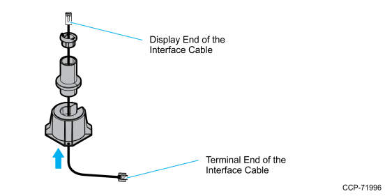
4.Route the display end of the Interface Cable through the Display Post, the Integration Pole, and the Display Swivel.
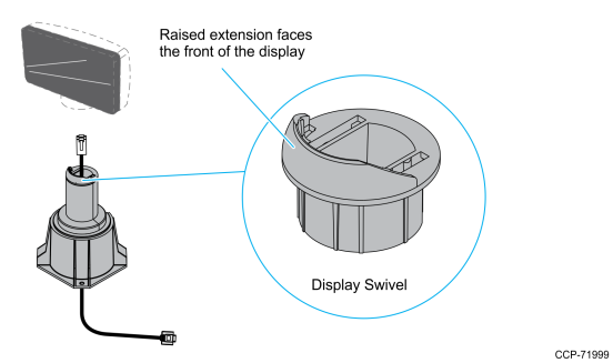
5.Assemble the post components.
Note: The raised extension of the Display Swivel is facing the front of the unit, which permits the Display to be tilted towards the back.
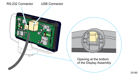
6.Connect the Interface Cable to the Display Module by inserting the Interface Cable through the opening at the bottom of the Display Assembly and to the designated connector on the Display Module.
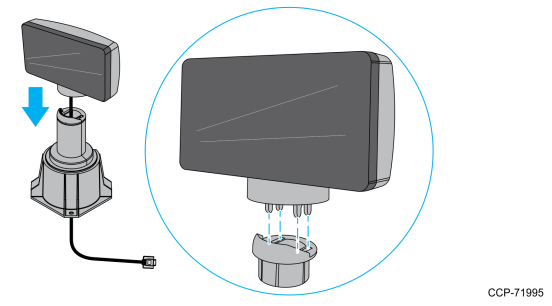
7.Connect the display to the post assembly.
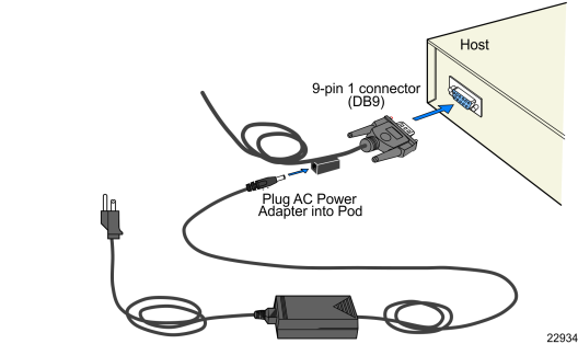
8.Connect the terminal end of the Display Cable to the host terminal.
•RS–232 Interface (Powered)
Connect the I/F cable to a powered RS–232 connector on the terminal.
•RS–232 Interface (Non–Powered)
Connect the I/F cable to a non–powered RS–232 connector on the terminal. Connect a Power Brick to the I/F cable and an AC outlet.
Configure the terminal serial port as follows:
9600 baud, 8 data bits, 1 start bit, 1 stop bit, No parity
•USB Interface (Powered)
Connect the I/F cable to a powered 12V USB + Power connector on the terminal.
•USB Interface (Non–Powered)
Connect the I/F cable to a non–powered USB connector on the terminal. Connect a Power Brick to the I/F cable and an AC outlet.