Upgrading the CPU
Upgrading the processor involves the following procedures:
Warning: Disconnect the AC power cord before disassembling the E-Box.
Caution: Static Electricity Discharge may permanently damage your system. Discharge any static electricity build up in your body by touching your computer’s case for a few seconds. Avoid any contact with internal parts and handle cards only by their external edges.
Removing the HDD
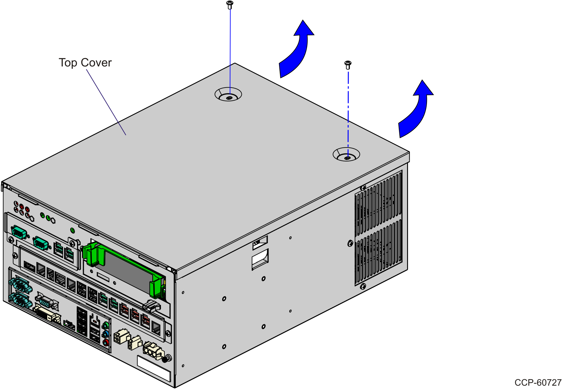
1.Loosen the screws (2) that secures the Top Cover.
2.Remove the Top Cover.
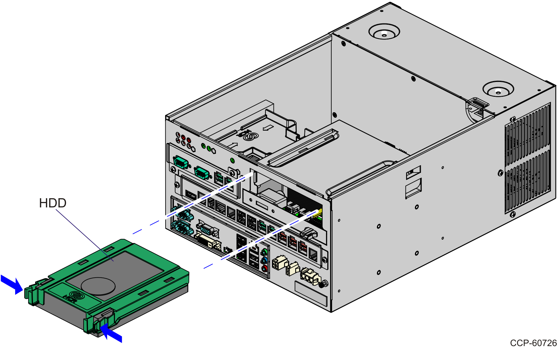
3.Squeeze the Release Tabs on the Hard Drive (HDD) Bracket and slide the assembly out of the slot.
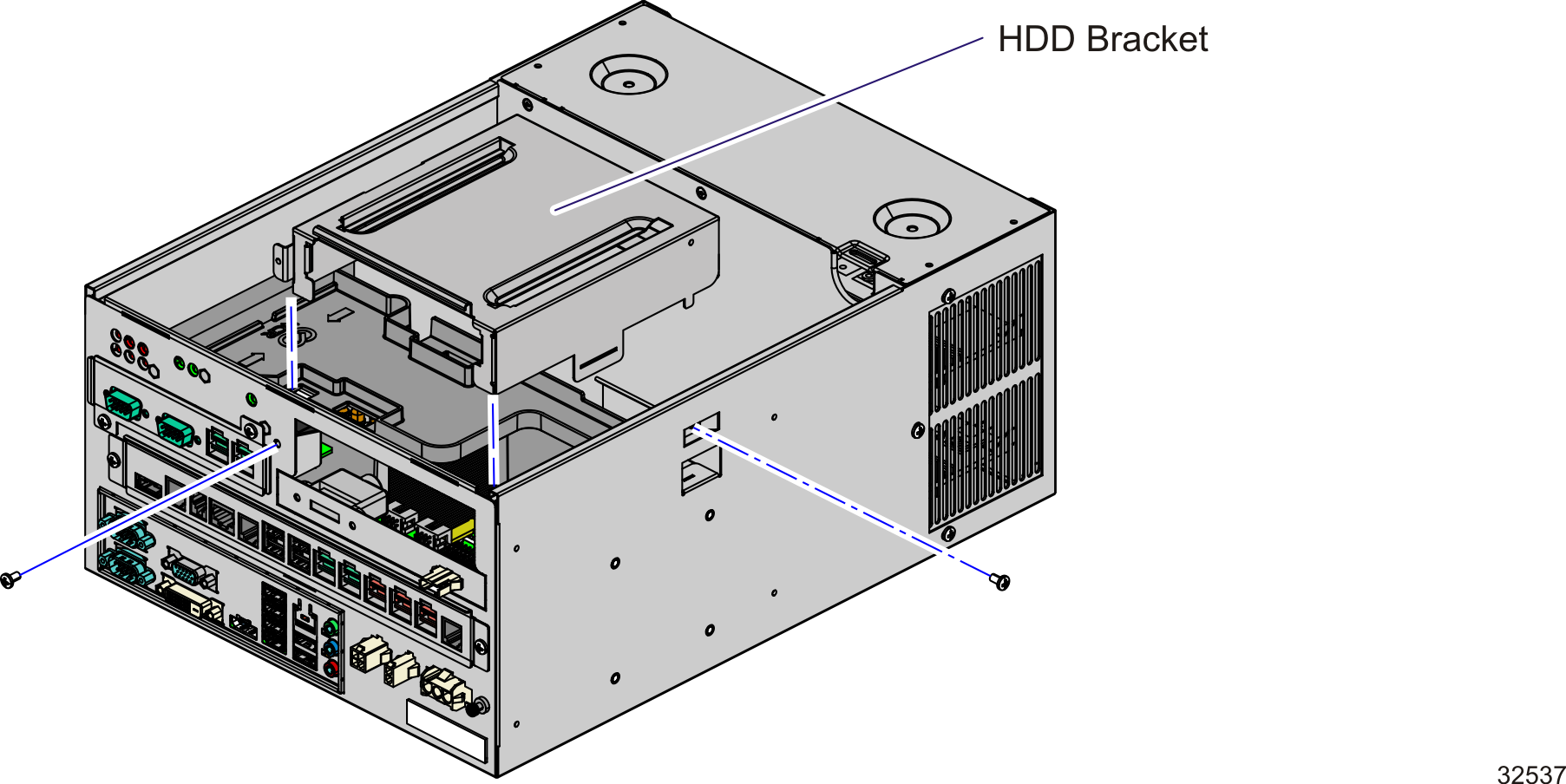
4.Remove the screws (2) that secure the HDD Bracket.
5.Remove the HDD Bracket from the E-Box.
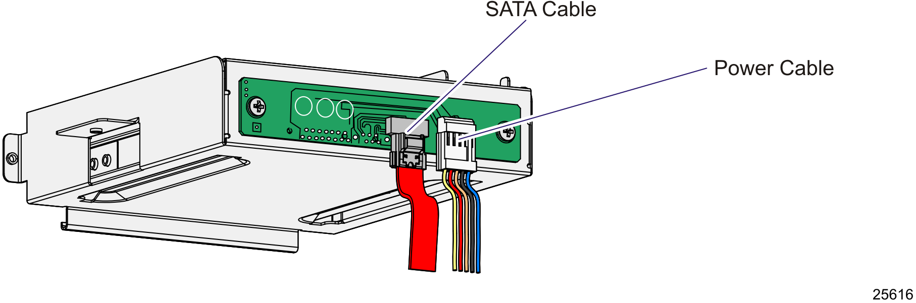
6.Disconnect the SATA Data and Power Cables from the PCB that is located on the rear of the HDD Bracket.
Removing the Processor
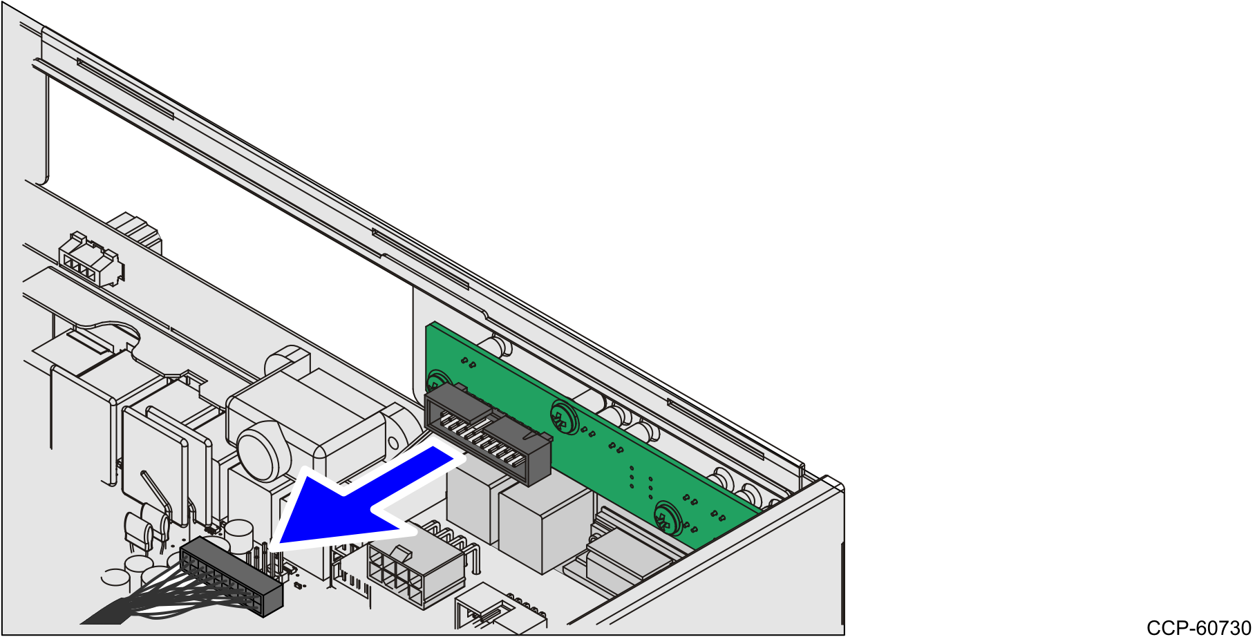
1.Disconnect the Box Header Connector Cable (black) from the LED and Power PCB Assembly.
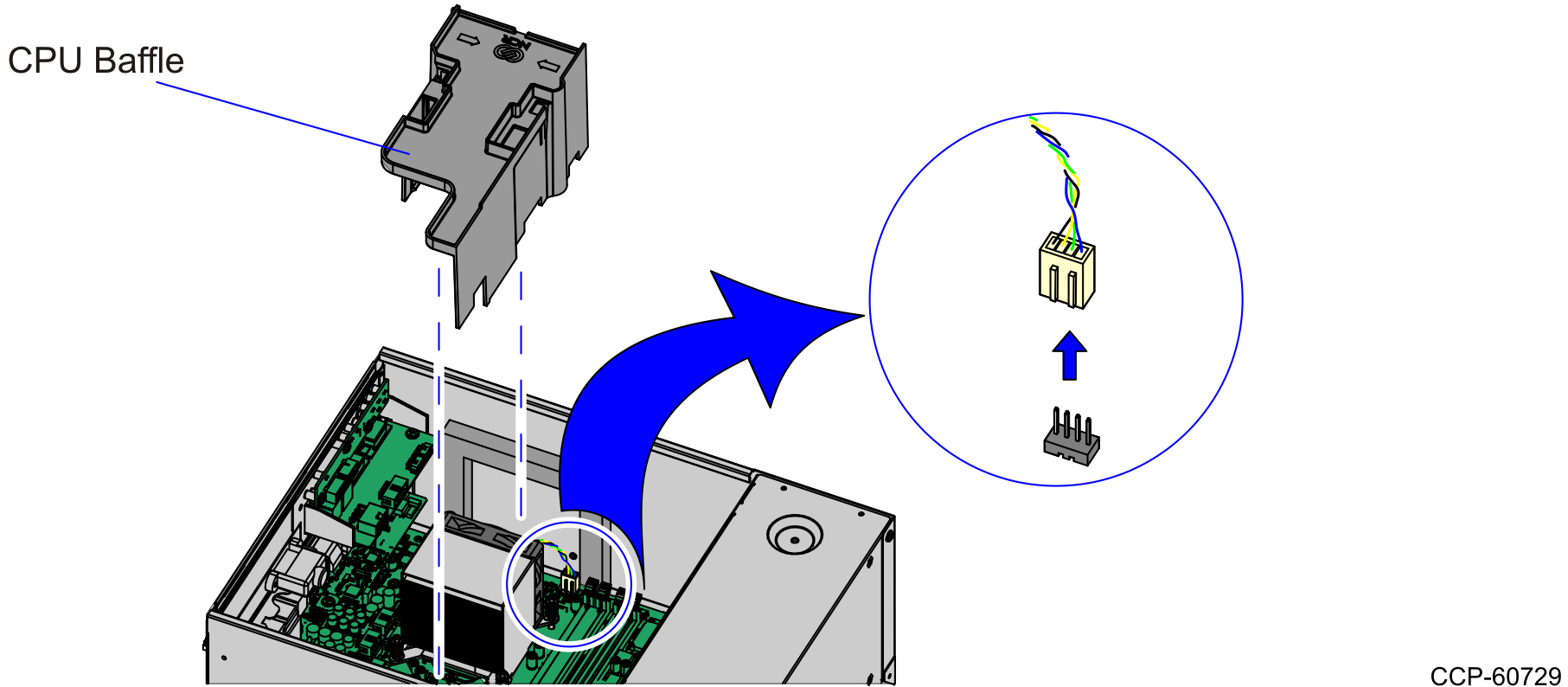
2.Remove the CPU Baffle from the motherboard.
3.Disconnect CPU Fan Header Connector from the motherboard.
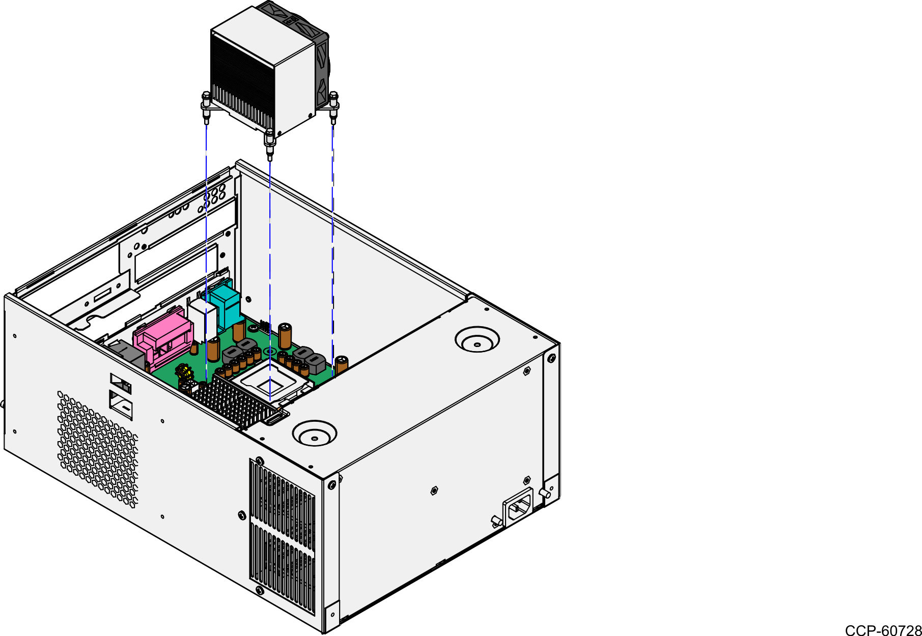
4.Loosen the spring-loaded screws (4) that secure the Heatsink with Fan Assembly to the Motherboard Assembly.
Note: Use a sequential rotating pattern when loosening the spring-loaded screws. Loosen each screw a little at a time to evenly raise the Heatsink from the CPU.
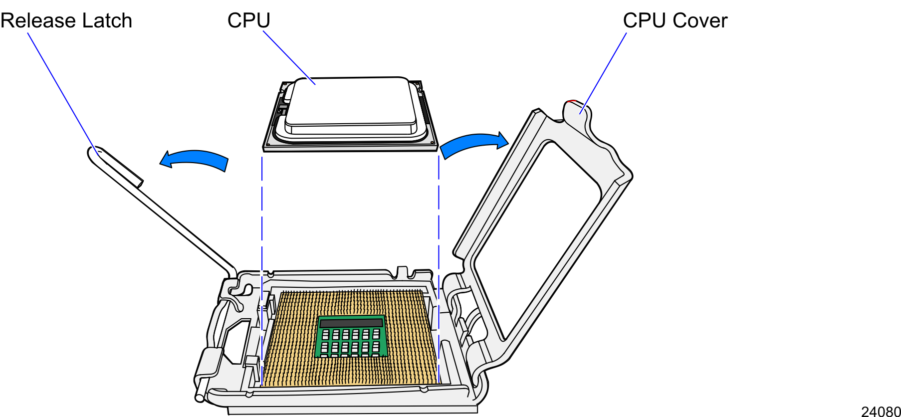
5.Remove the CPU from the Motherboard by doing the following:
a.Press down on the Release Latch to release CPU cover.
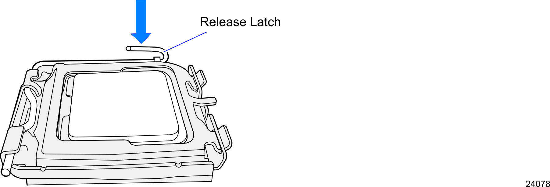
b.Open the CPU Cover.
c.Gently remove the CPU from the socket.
Replacing the Processor
1.Correctly position the new CPU over the CPU Socket by aligning the two notches on the CPU with the tabs in the socket. (Pin 1 of the CPU must align with Pin 1 on the socket.)
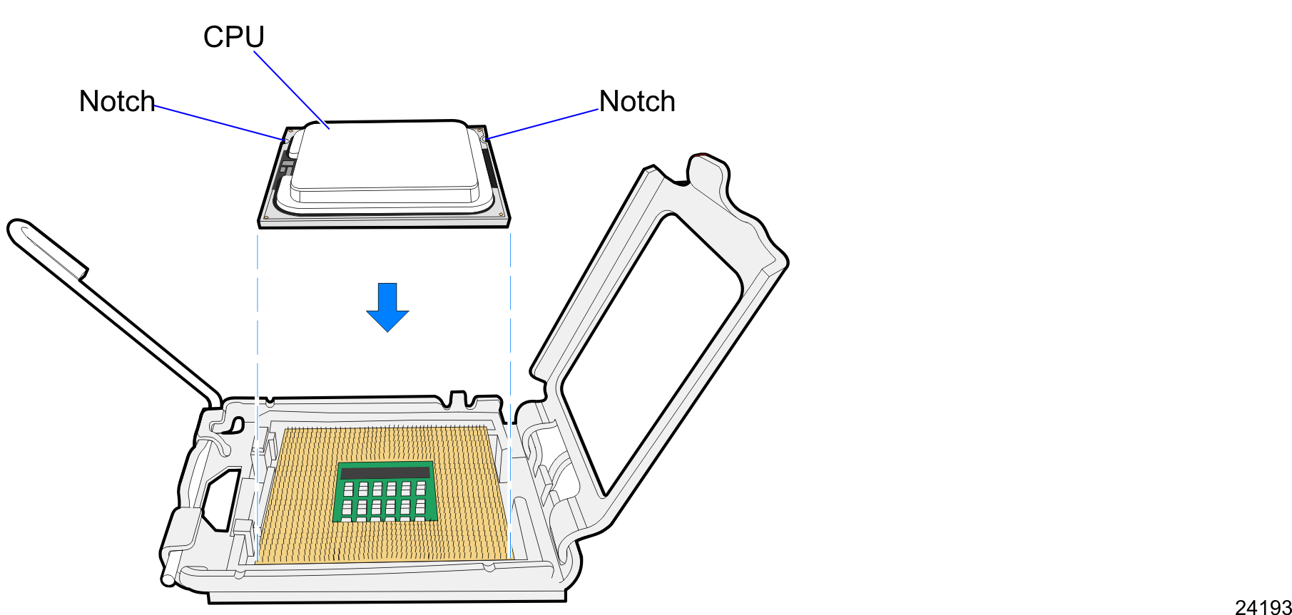
Note: Do not insert the CPU at an angle. Do not force the CPU into the socket, place it on its own weight.
2.Apply Thermal Grease on the CPU surface.
3.Gently close the clover.
4.Look the CPU in the socket with the Latch.
5.Install the Heatsink.
Note: Use the same sequential pattern when tightening the spring-loaded screws.
6.Insert the CPU Baffle.
7.Connect the Box Header Connector Cable to the LED and Power PCB Assembly.
8.Connect the SATA Data and Power Cables to the connectors located at the rear of the HDD Bracket.
9.Install the HDD Bracket to the E-Box using the screws (2).
10.Slide the HDD Assembly into the HDD Bracket. Make sure that it is snapped to the slot.
11.Install the cover and secure it with screws (2).