Routing Tri-Light/Lane Light Cable on a Card Only unit
To route the Tri-Light cables in a Card Only unit, follow these steps:
- Do the following:
- From the pole duct, route the Tri-Light/Lane Light cable down through the built-in hooks inside the Tower Frame.
- Route the cable down the Scanner/Scale bucket floor. Use cable ties to secure the cable on bridge lances.
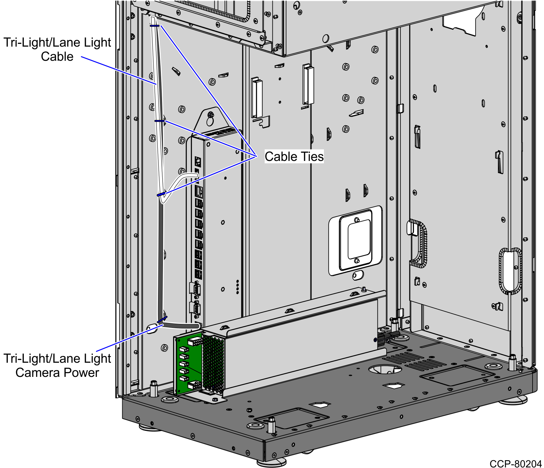
- Secure the cable to the anchor using a cable tie.
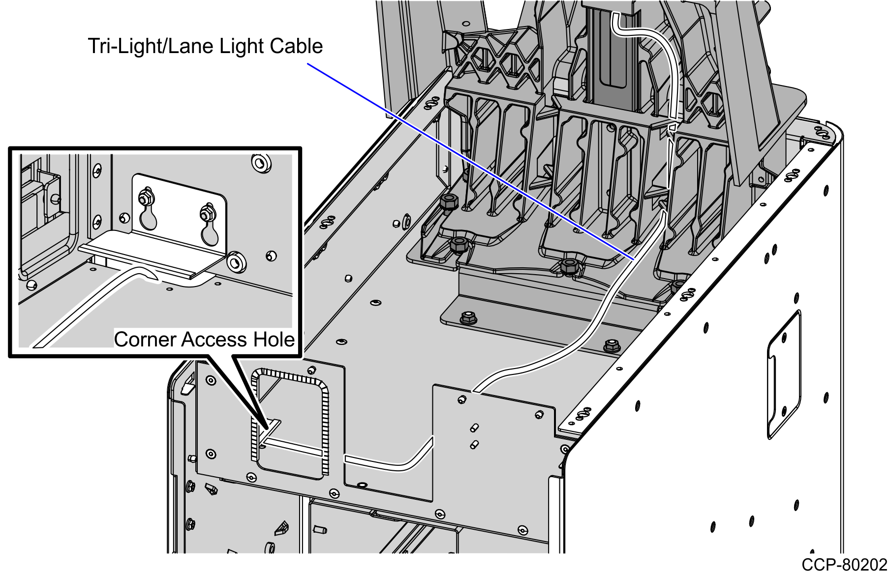
- From the corner cable access hole, route the cable down the Core Cabinet wall.
- Depending on the configuration, connect the Tri-Light cable to the Tri-Light/Lane Light port. Use cable ties to tie the cable on bridge lances.
- KIO and 150 W PSU Configuration
- I/O Box Configuration
KIO Board and 150 W PSU Configuration
Note
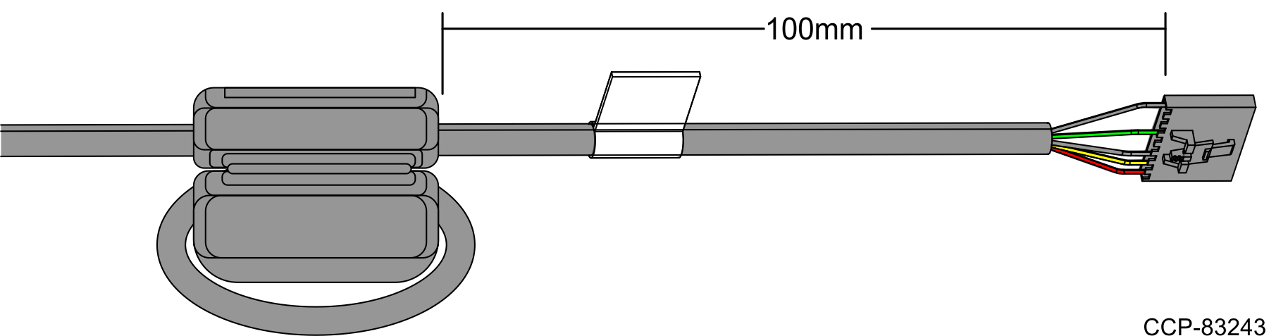
Units with KIO Board and 150 W PSU Configuration use a Tri-Light cable with ferrite.
- Measure at least 100 mm length from the Tri-Light connector and make one (1) cable loop around the ferrite core, and then clamp the cable with the ferrite.
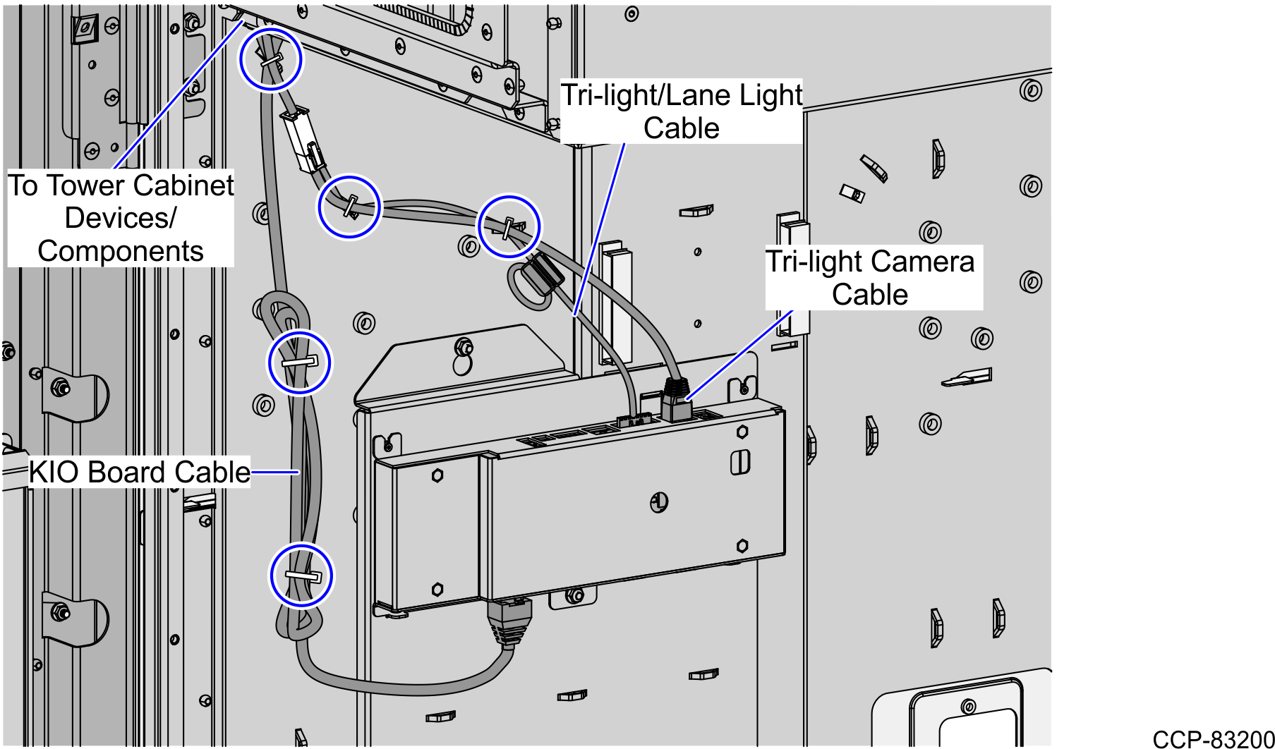
- Connect the Tri-Light cable to its corresponding port in the KIO Board.Note
For the Tri-Light/Lane Light with Camera Assembly, mate the Camera Power cable to the Tri-Light Camera 12 V Power Cable, and then connect the cable to the CAB/TAB Port of the KIO Board.
I/O Box Configuration
Note
For the Tri-Light/Lane Light with Camera Assembly, connect the Camera Power cable to the I/O Box (Input Belt port).