Routing the 7896 Scanner/Scale Cables
The Scanner/Scale Power cable is the same cable for both the 7895 Scanner/Scale and 7896 Scanner/Scale. It is pre-routed inside the Self-Checkout unit.
The Color Camera USB Cable is different for each Scanner/Scale and it is not shipped with the either the 7895 Scanner/Scale or 7896 Scanner/Scale. It is purchased separately and needs to be installed during the initial setup of the Scanner/Scale. To route the cables and connect the Color Camera cable to the Scanner/Scale and Terminal Display, follow these steps:
When routing cables, ensure that the Color Camera cable is as far as possible from the Sensormatic® cables to avoid signal interference between the Sensormatic® EAS system and the Color Camera. Contact an NCR Representative about the Sensormatic Antenna for the 7895/7896 NCR Voyix Scanner/Scale.
Only authorized personnel from Sensormatic® can install the Sensormatic® Antenna in the field.
Open the Tower Frame. For more information, refer to Opening the Tower Frame.
- Do the following:
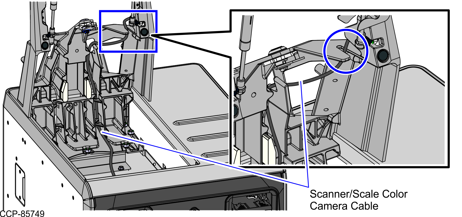
- Route the Color Camera cable through the 7360 R6C Tower Frame ribs.
- Insert the cable through the "zig-zag" routing provision on the Tower Frame, as shown the image below.Note
Ensure that there is enough cable slack to avoid cables from being stretched during installation or removal procedures. Provide at least 90 cm (35 in) of cable length/slack from the bottom of the "zig-zag" routing provision.
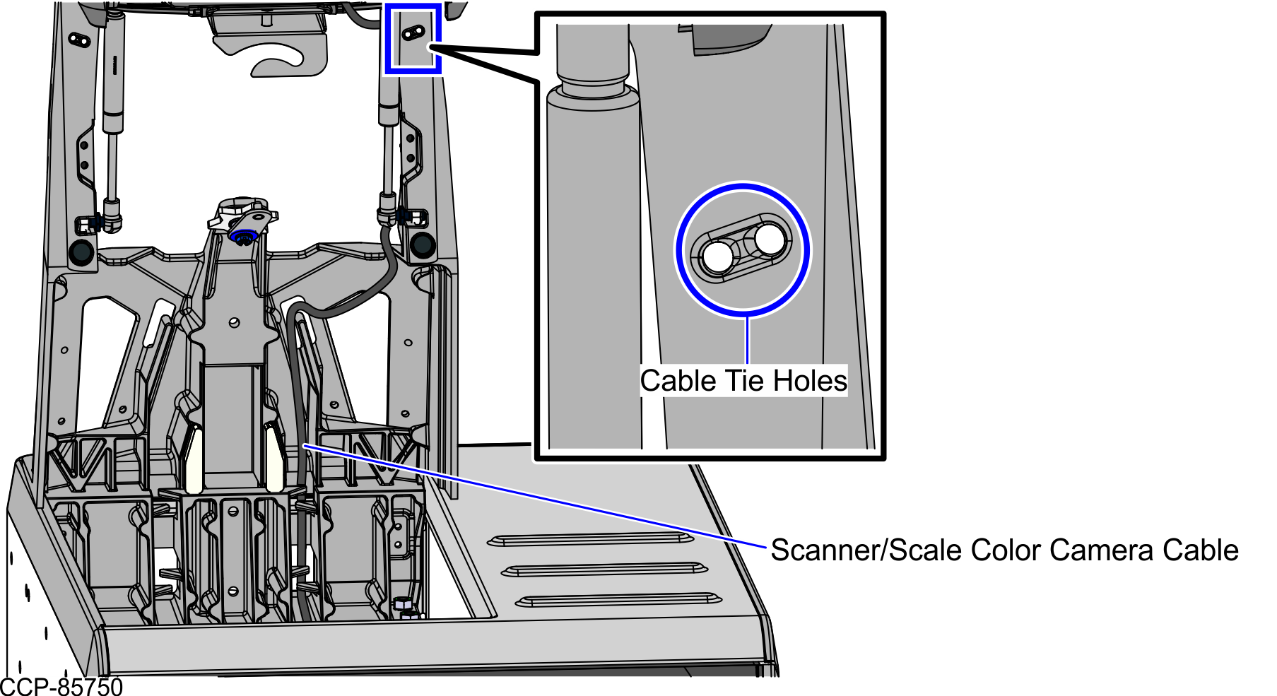
- Continue to route the Color Camera cable along with the other cables going up the Tower Frame and through the Tower Side Channel, as shown in the image below.
- Secure the cables using a cable tie that is inserted through the holes on the Tower Frame.
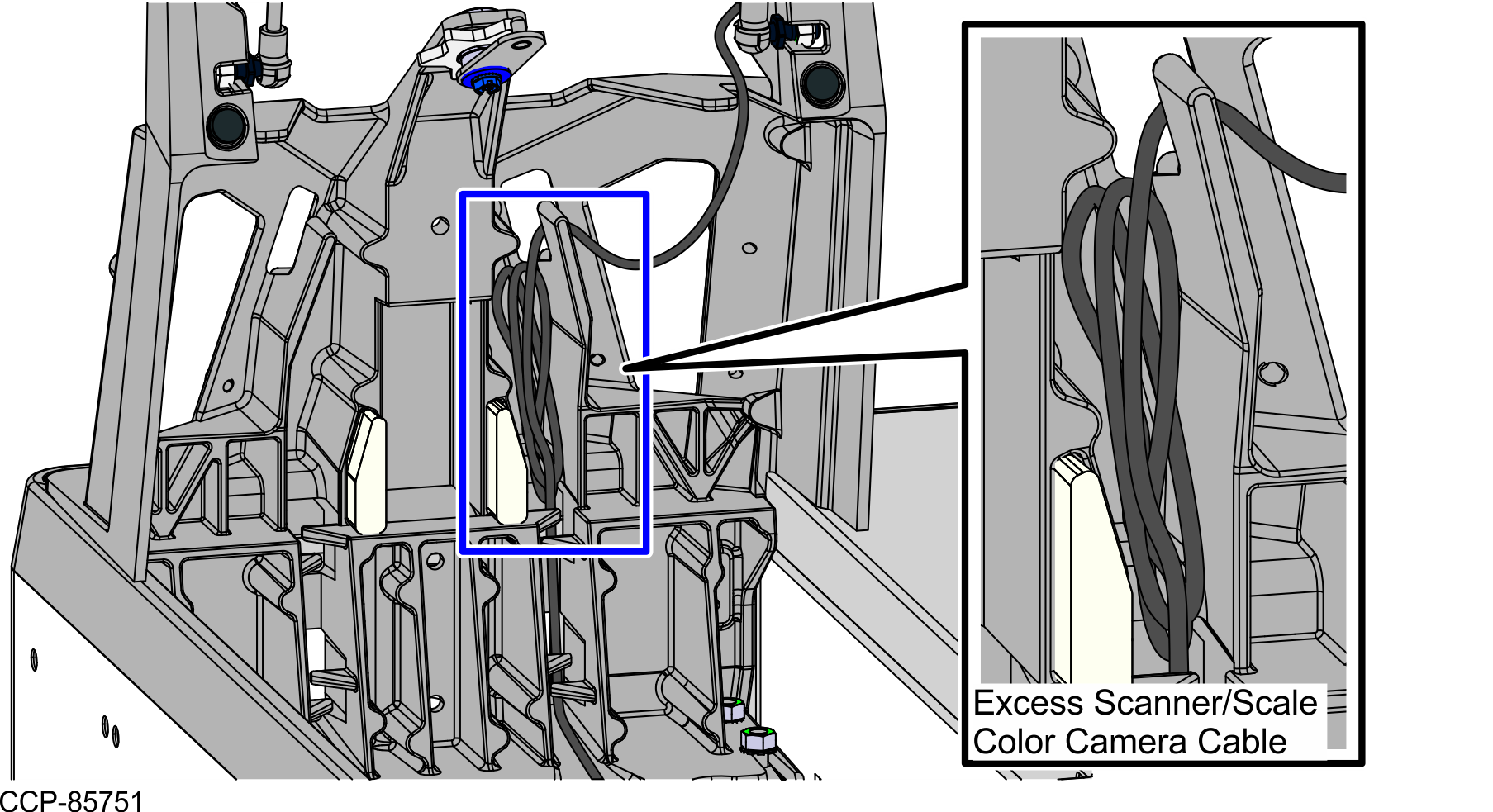
- Insert excess cable into the space adjacent to the Tower Frame pole duct.
- Do the following:
- Route the Scanner/Scale Power cable and Color Camera cable through the side of the Display Hinged Bracket and secure using cable ties, as shown in the image below.Note Apply enough slack to the cables so that they can move with the Terminal Display.
- Connect the cables to the Terminal Display.
Scanner/Scale Cable Terminal Display Port Scanner/Scale Power Cable Port C Scanner/Scale Color Camera Cable Port B (USB 3.0)
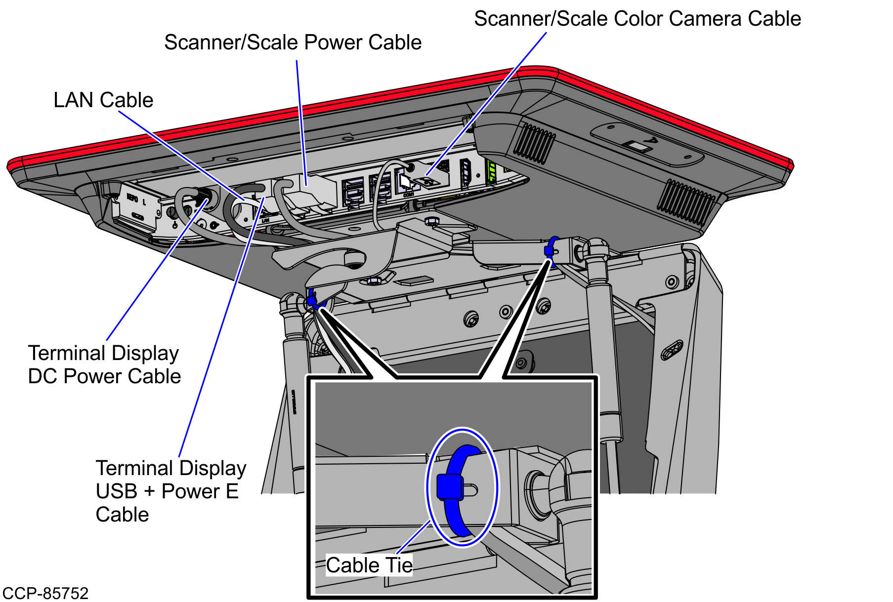
- Route the Scanner/Scale Power cable and Color Camera cable through the side of the Display Hinged Bracket and secure using cable ties, as shown in the image below.
- Connect the cables to the 7896 Scanner/Scale by doing the following:
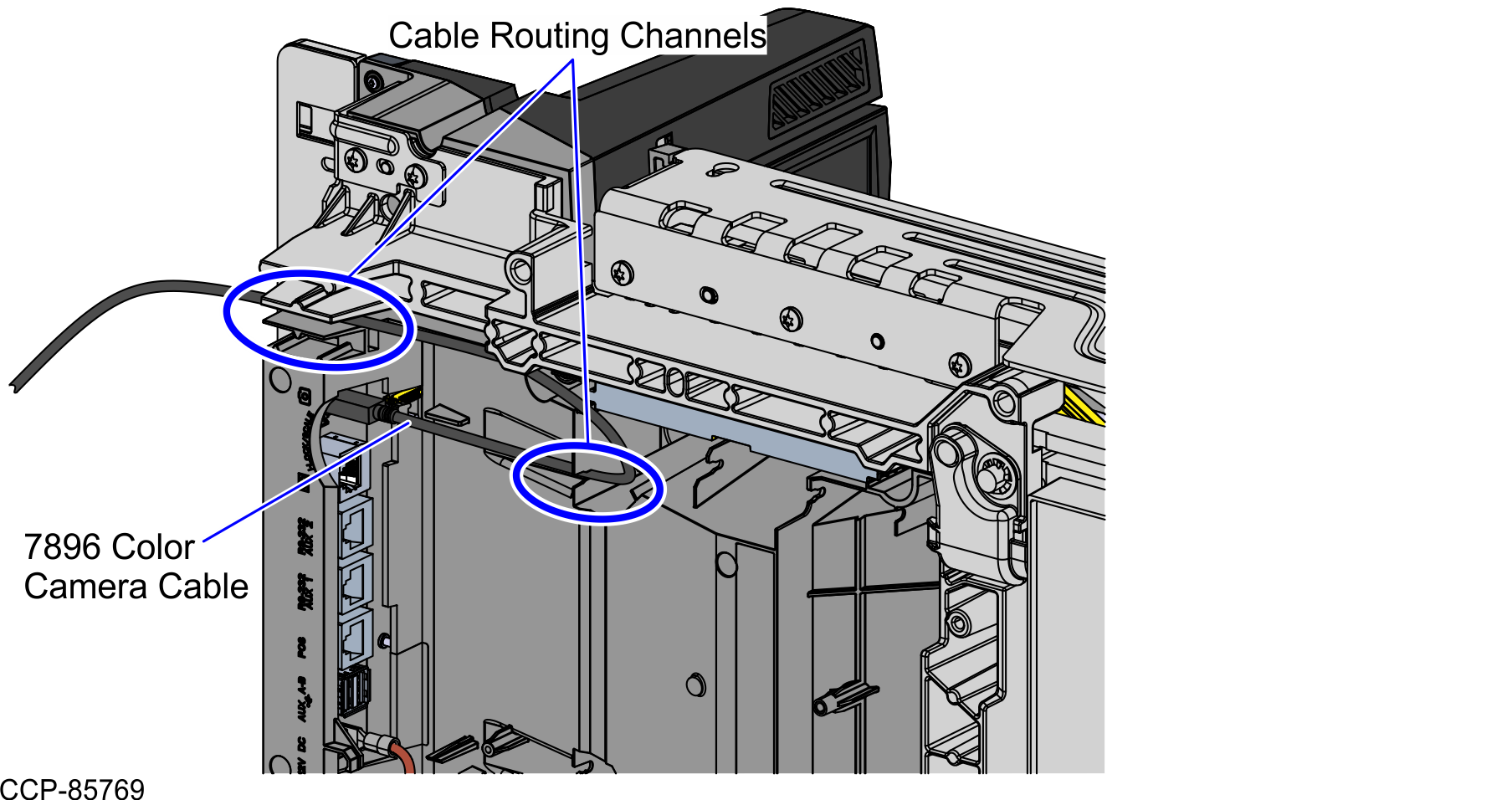
- Plug the Color Camera cable to the 7896 Scanner/Scale USB Type C port.
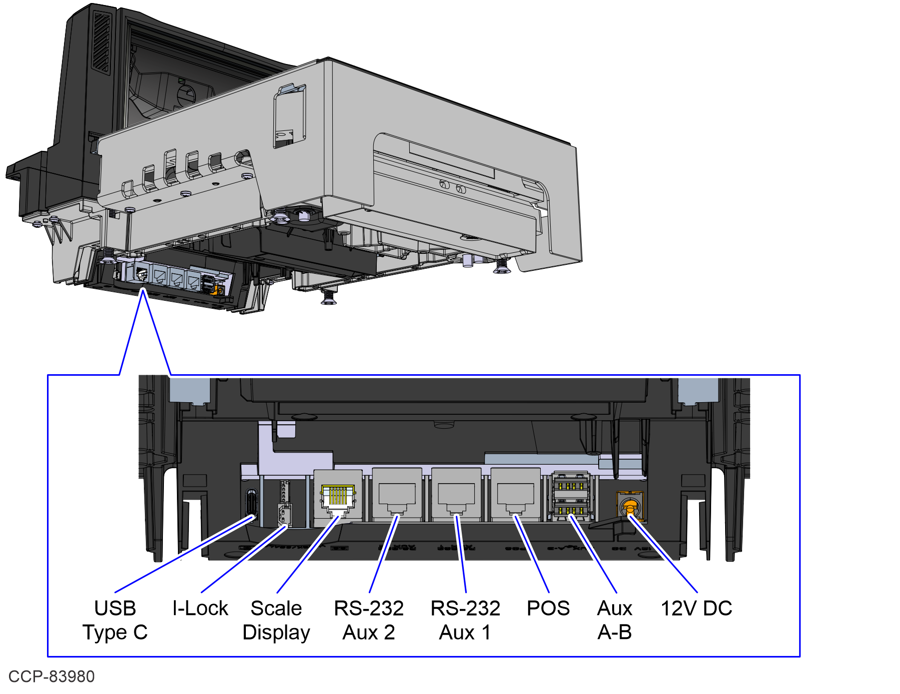
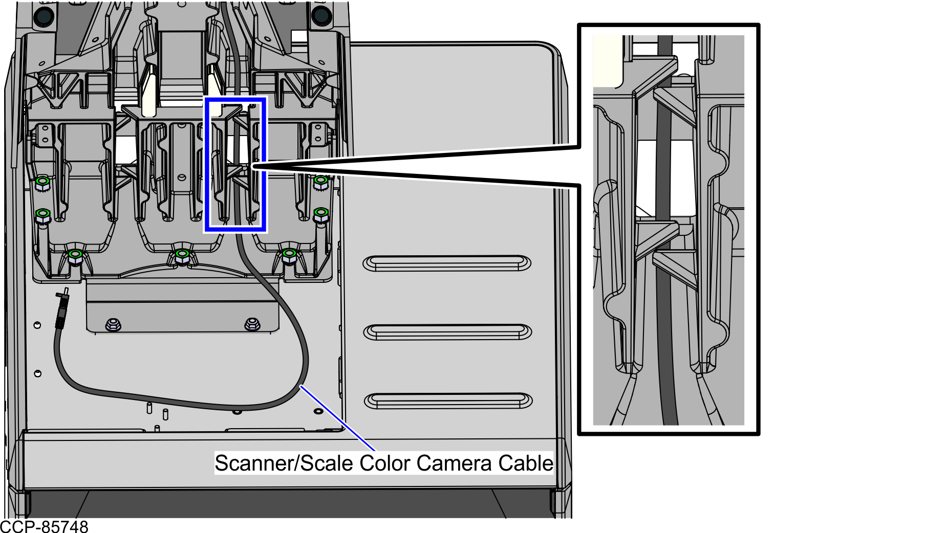
- Route the Color Camera cable through the cable routing channels under the Scanner/Scale, as shown in the image below.
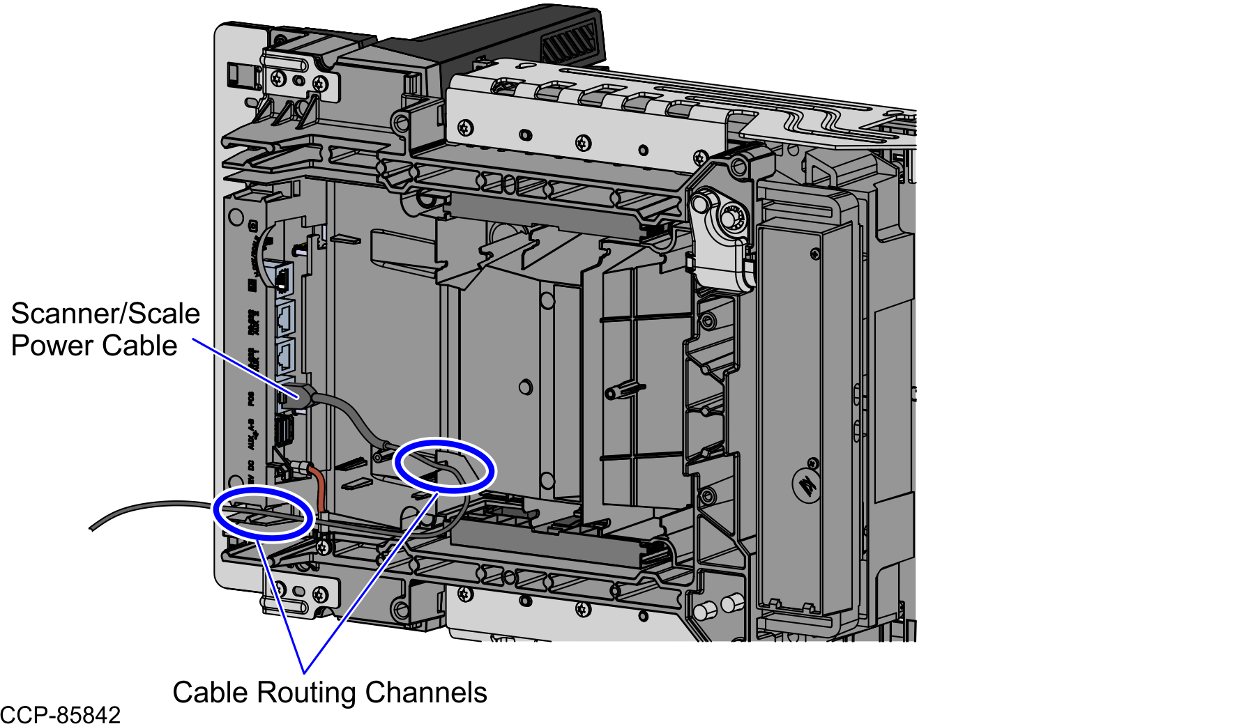
- Plug the Power cable to the 7896 Scanner/Scale POS port.
- Route the Power cable through the cable routing channels under the Scanner/Scale, as shown in the image below.
- Plug the Color Camera cable to the 7896 Scanner/Scale USB Type C port.
