Routing the Cables: 7358 R6L Plus
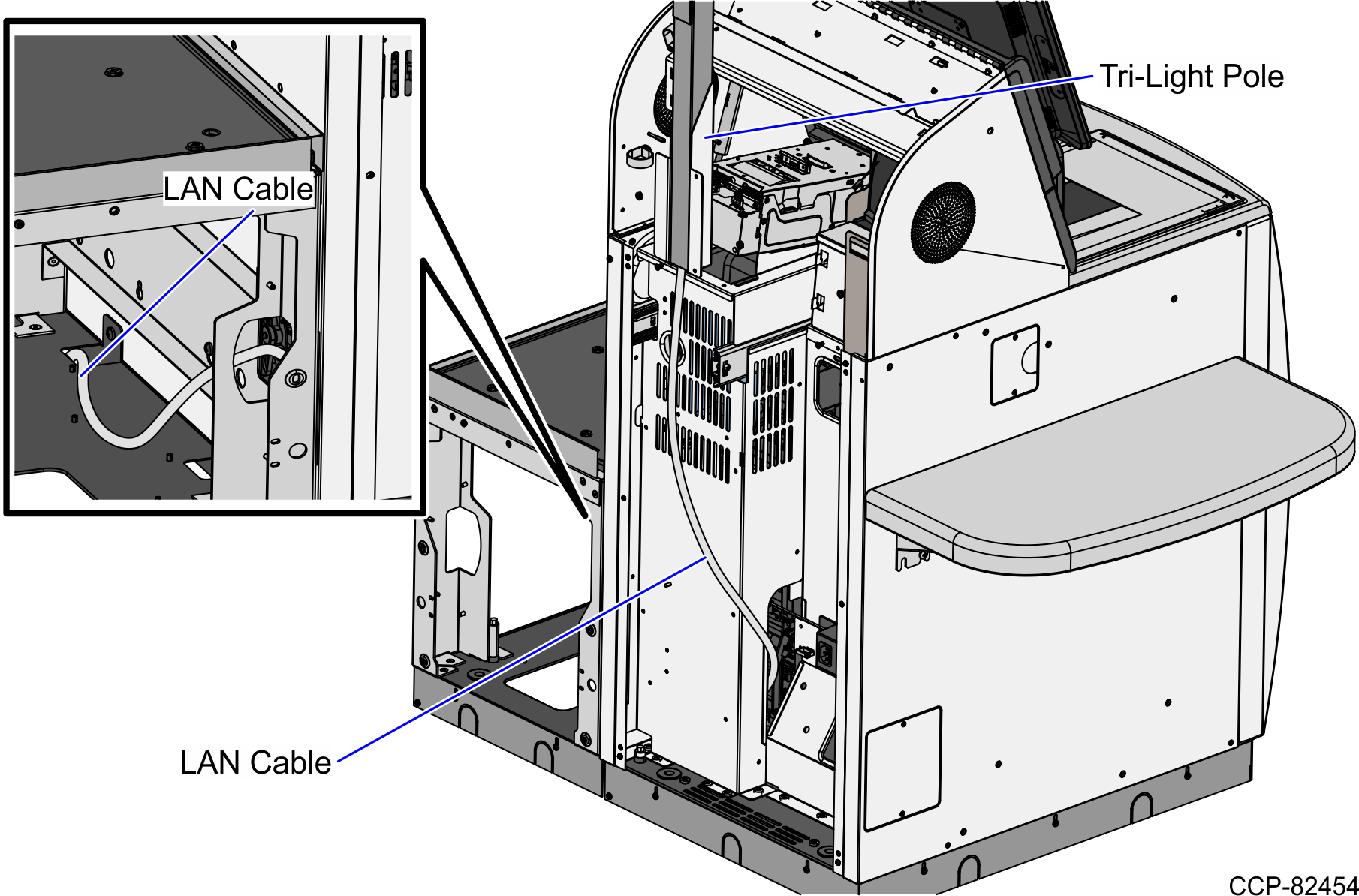
To route the Tri-Light/Lane Light Cable and the LAN Cable in the 7358 unit, follow these steps:
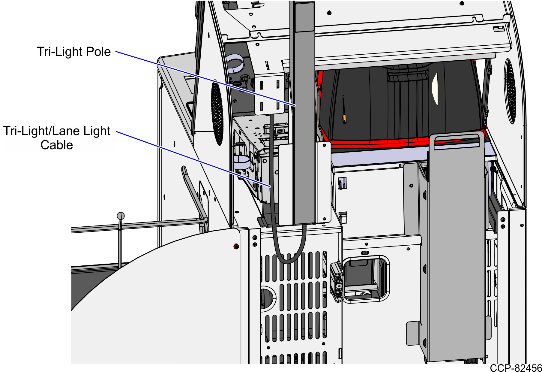
- Route the Tri-Light/Lane Light Cable by doing the following:
- From the Tri-Light/Lane Light Pole, route the cable up into the Upper Cabinet. Note
Apply enough cable slack to prevent the cable from being stretched during installation or removal procedures.
- Secure the cable to the Upper Cabinet frame using cable ties.
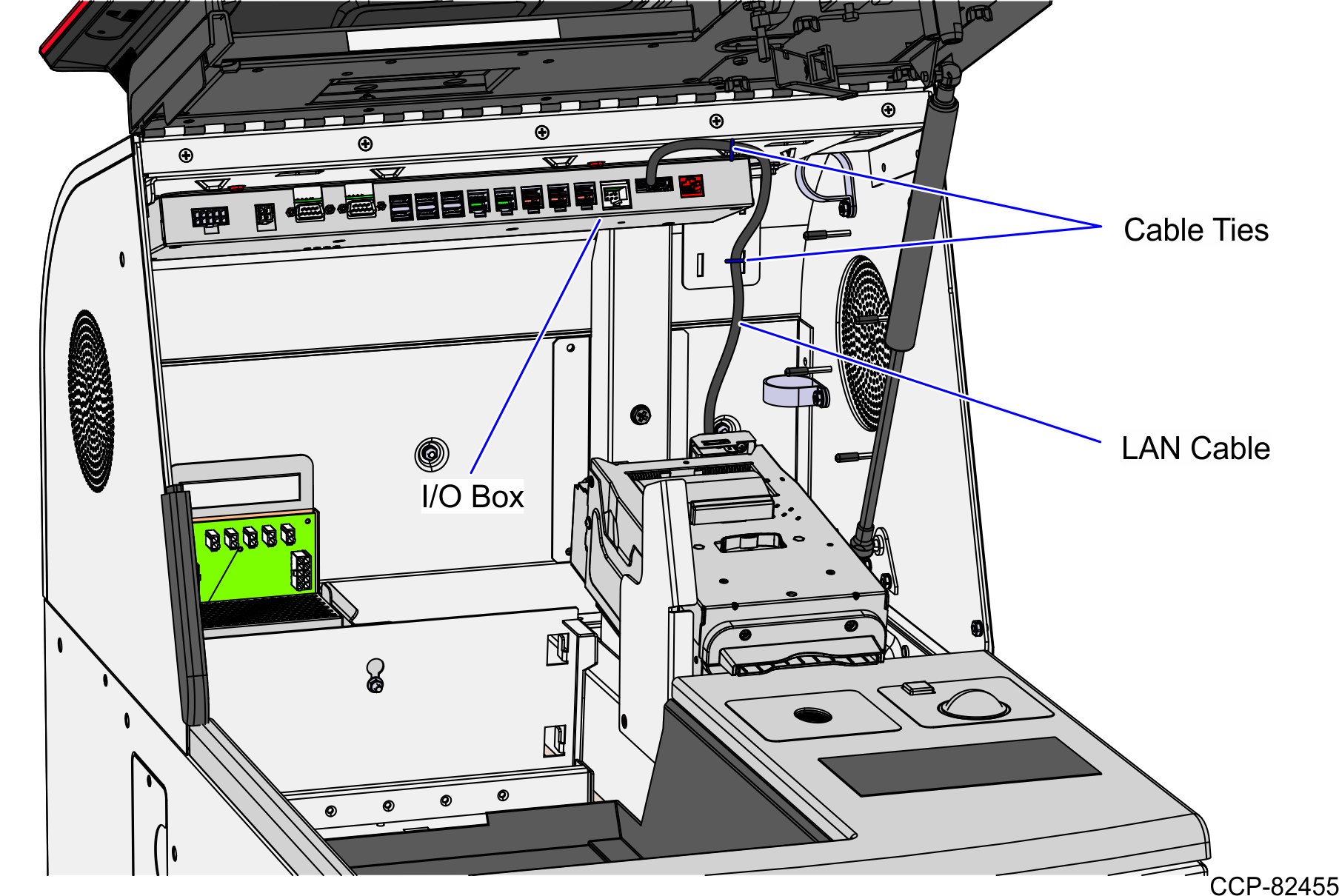
- Connect the cable to the Tri-Light/Lane Light port of the I/O Box.
- Route the LAN Cable. Depending on the unit configuration, refer to the following:
- From the Tri-Light/Lane Light Pole, route the cable up into the Upper Cabinet.
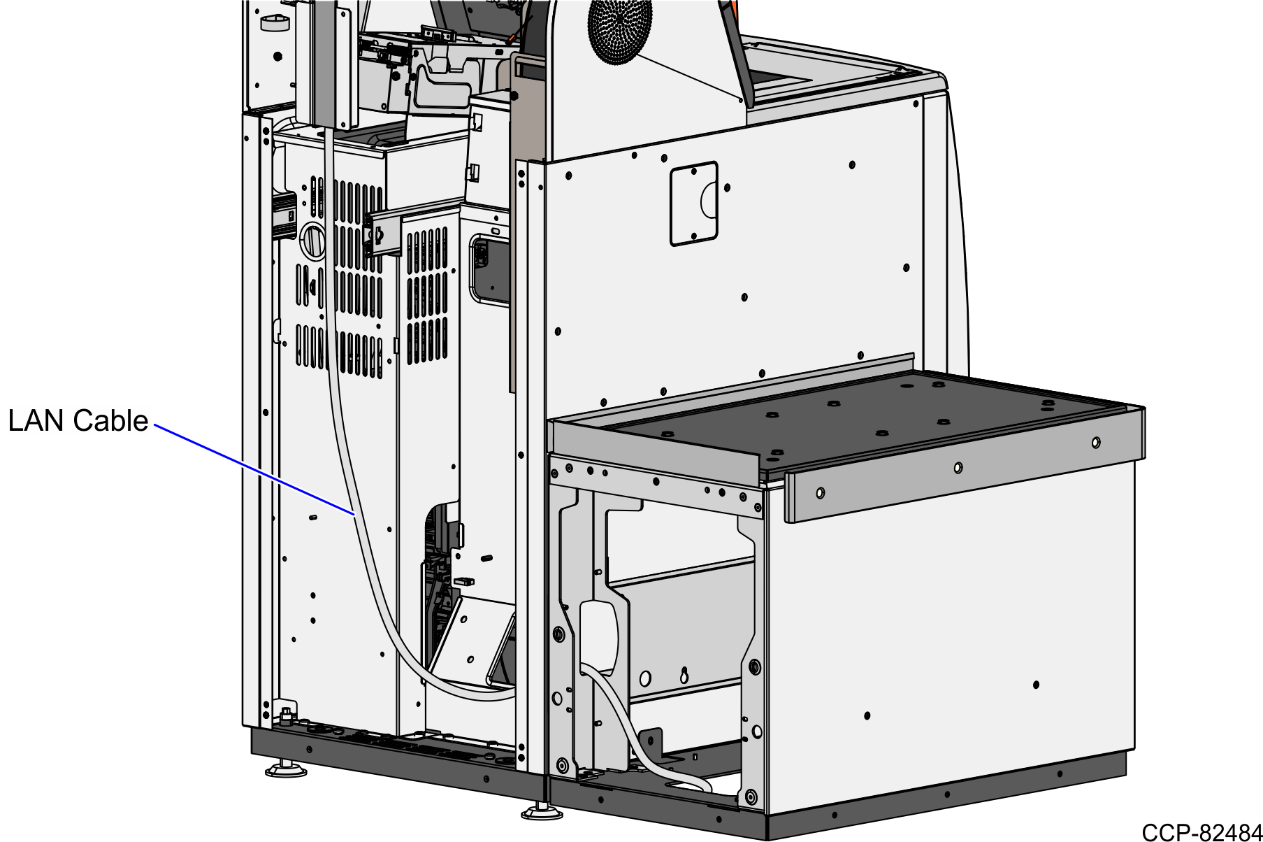
No-Bag Unit: 7358 R6L Plus
To route the LAN Cable, follow these steps:
- From the Tri-Light/Lane Light Pole, route the cable down the rear of the Core Cabinet and out through the side cable exit hole.Note
The LAN Cable can exit either through the left or the right side cable exit hole depending on the customer's preference.
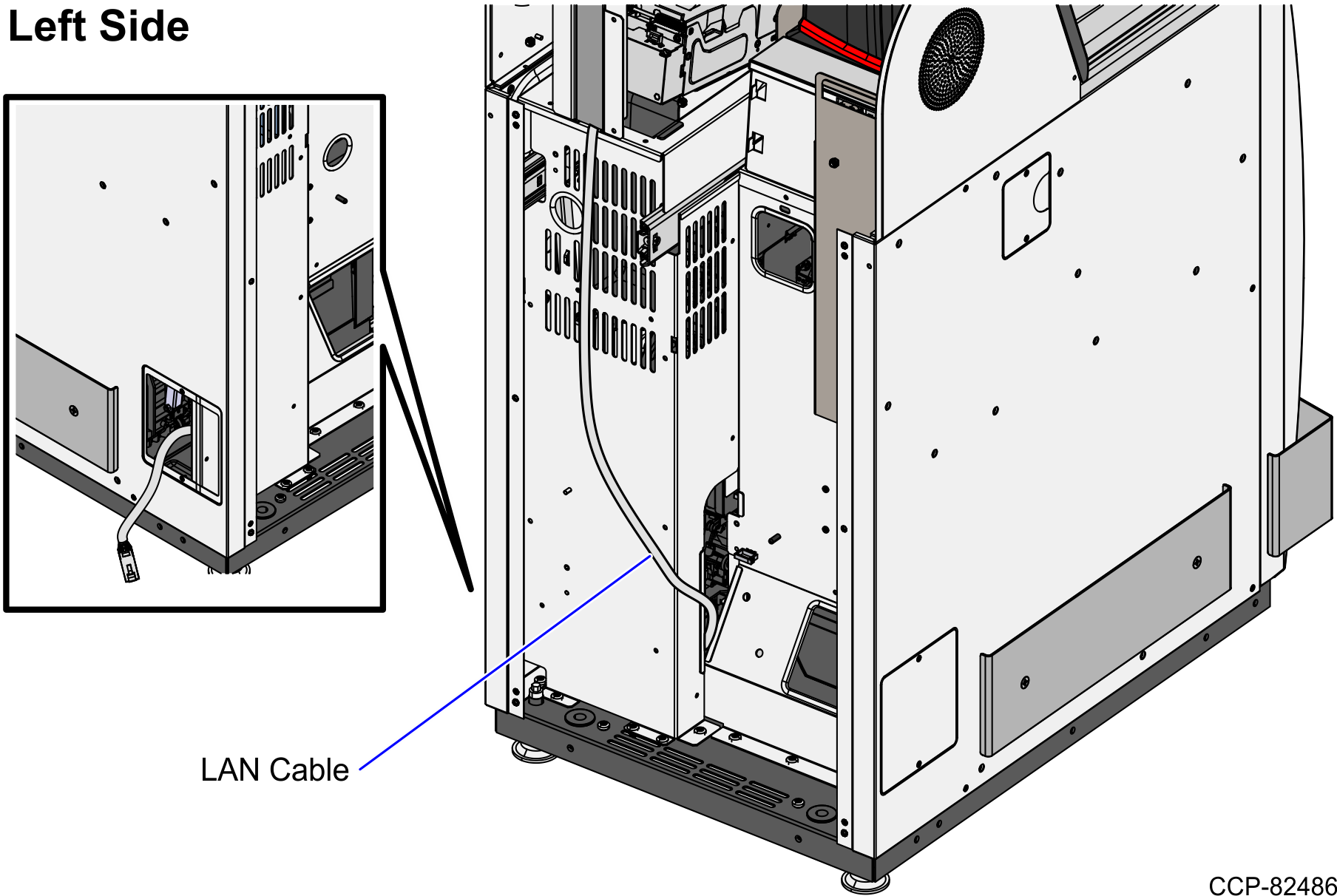
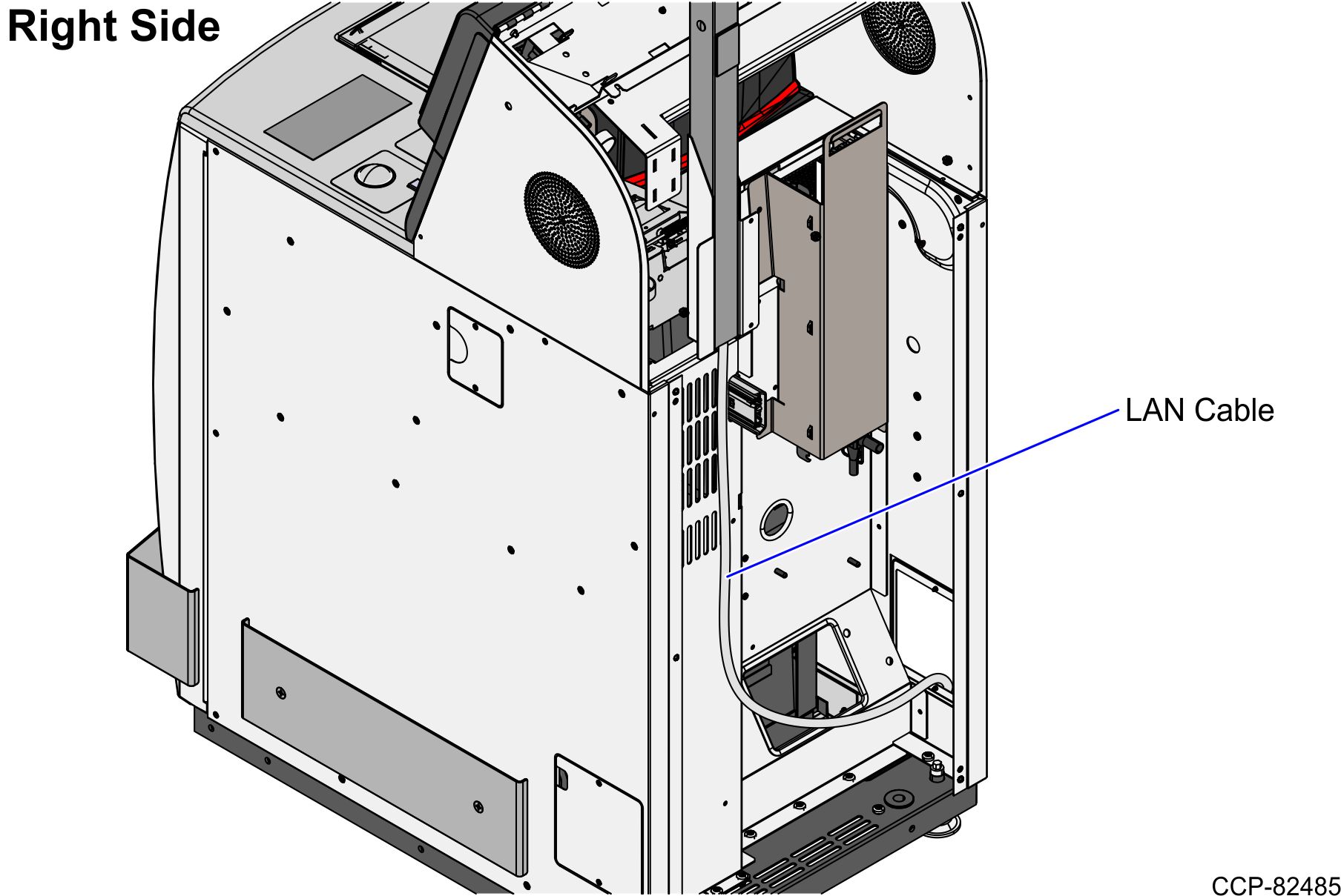
Connect the cable to the PoE Switch.
Left-Hand Unit: 7358 R6L Plus
To route the LAN Cable, follow these steps:
- From the Tri-Light/Lane Light Pole, route the cable down the rear of the Core Cabinet, through the side cable exit hole and into the Bagwell
- Pass the cable through the bottom cable exit hole of the Bagwell.
- Connect the cable to the PoE Switch.
Right-Hand Unit: 7358 R6L Plus
To route the LAN Cable, follow these steps:
- From the Tri-Light/Lane Light Pole, route the cable down the rear of the Core Cabinet, through the side cable exit hole and into the Bagwell
- Pass the cable through the bottom cable exit hole of the Bagwell.
- Connect the cable to the PoE Switch.
