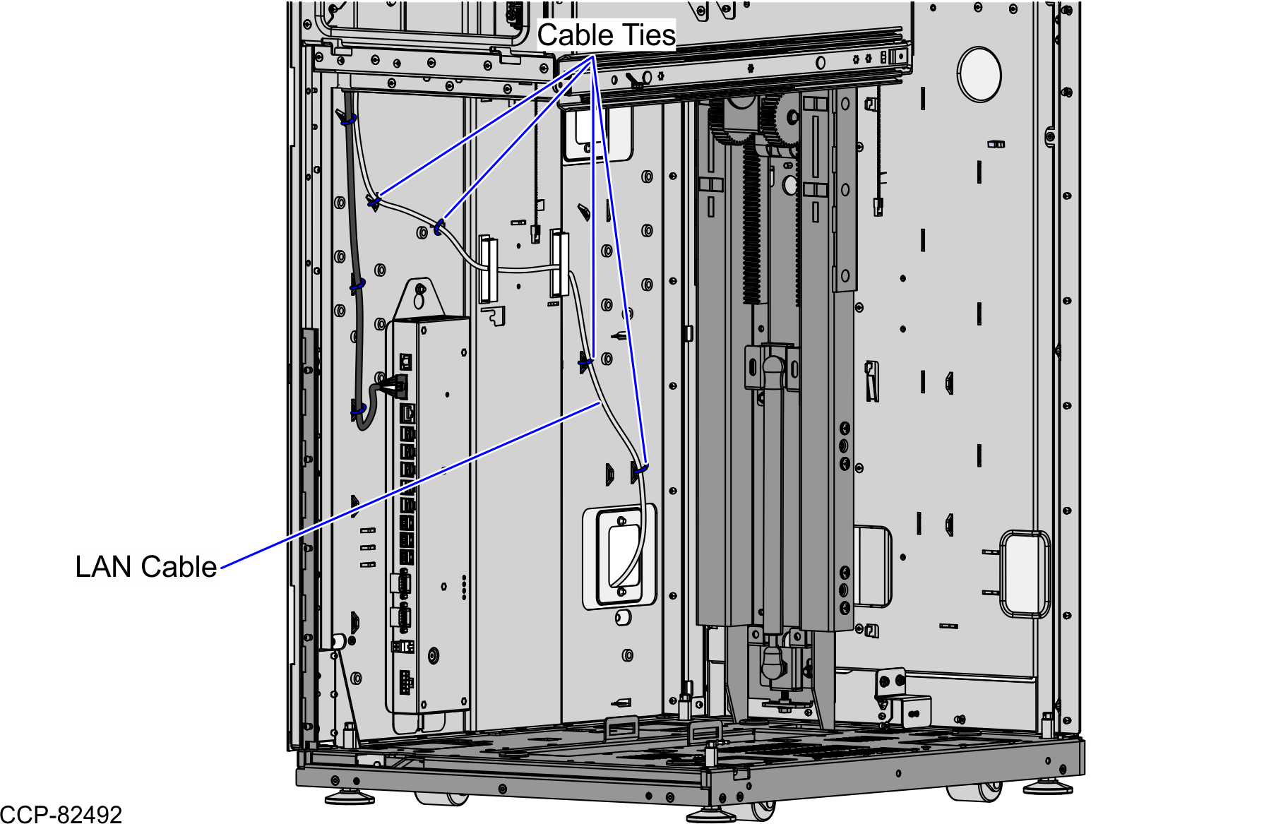
Routing the Cables: 7360 R6-C Full Function (Convertible)
To route the Tri-Light/Lane Light Cable and LAN Cable in the 7360 Full Function (Convertible) unit, follow these steps:
- Do the following:
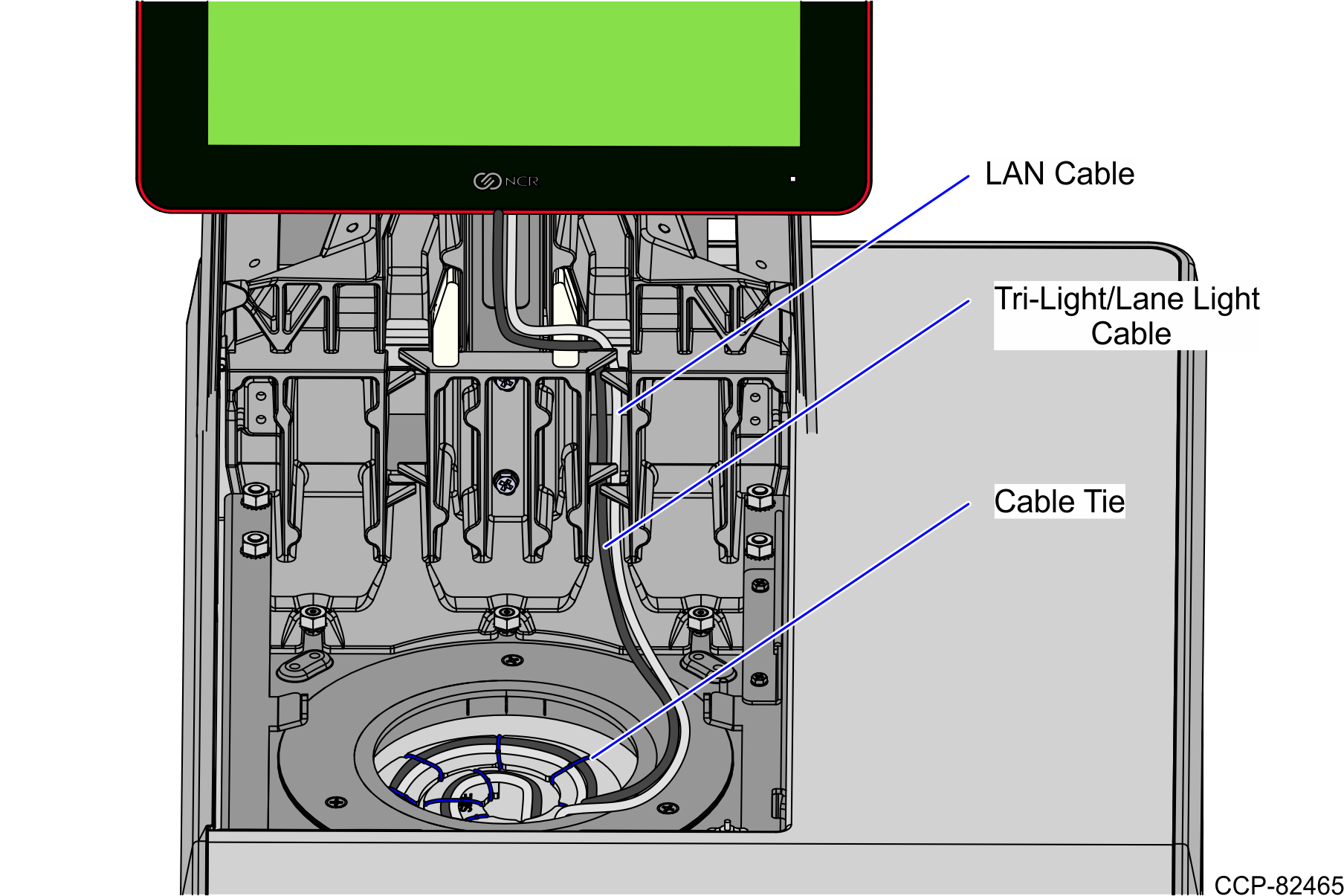
- From the Tower Frame pole duct, route the Tri-Light/Lane Light Cable and the LAN Cable down through the built-in hooks inside the Tower Frame.
- Route the cables down the opening of the Scanner Lift Assembly along the Spiral Management Cable.
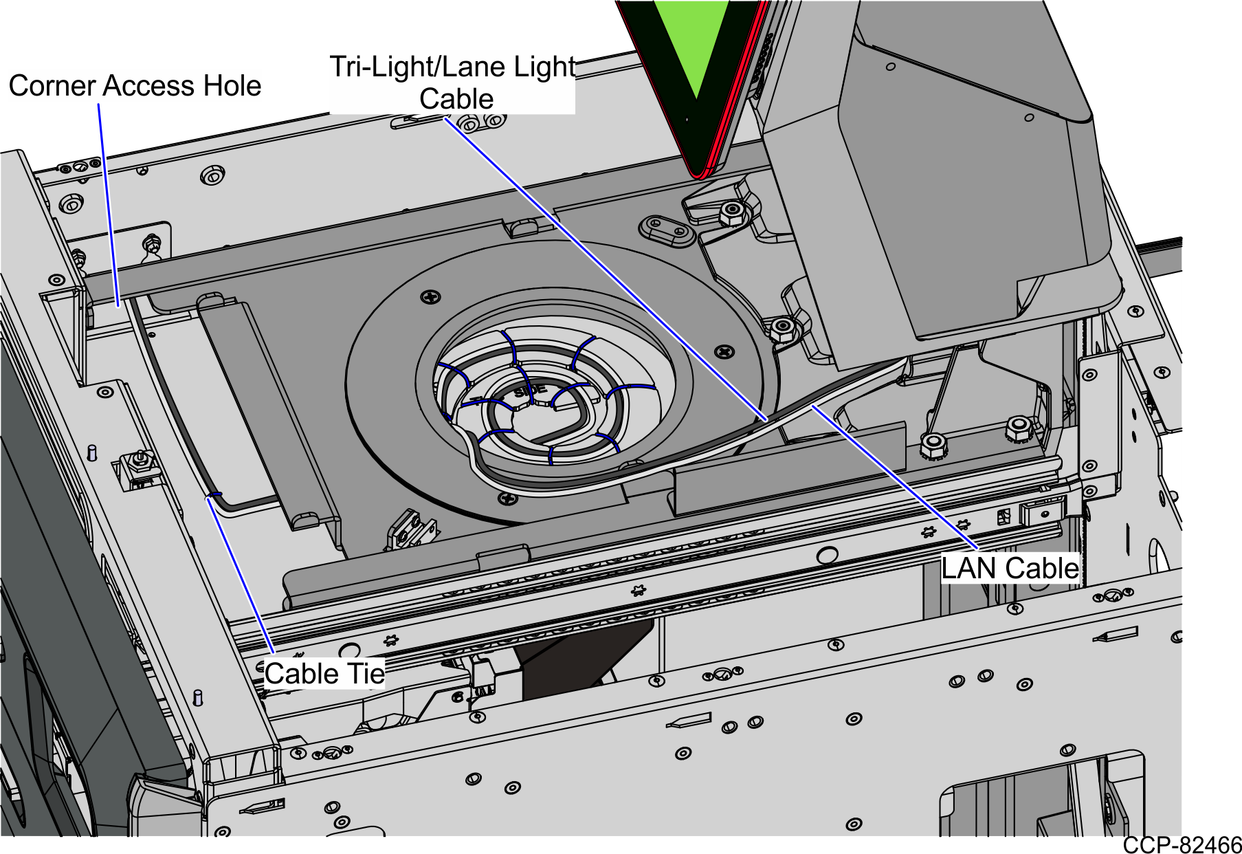
- Secure the cables by placing cable ties on every notch on the Spiral Management Cable.
- Continue to route the cables into the corner cable access hole.
- Route the Tri-Light/Lane Light Cable by doing the following.
- From the corner cable access hole, route the cable down the Core Cabinet wall and use cable ties to secure the cables on the bridge lances.
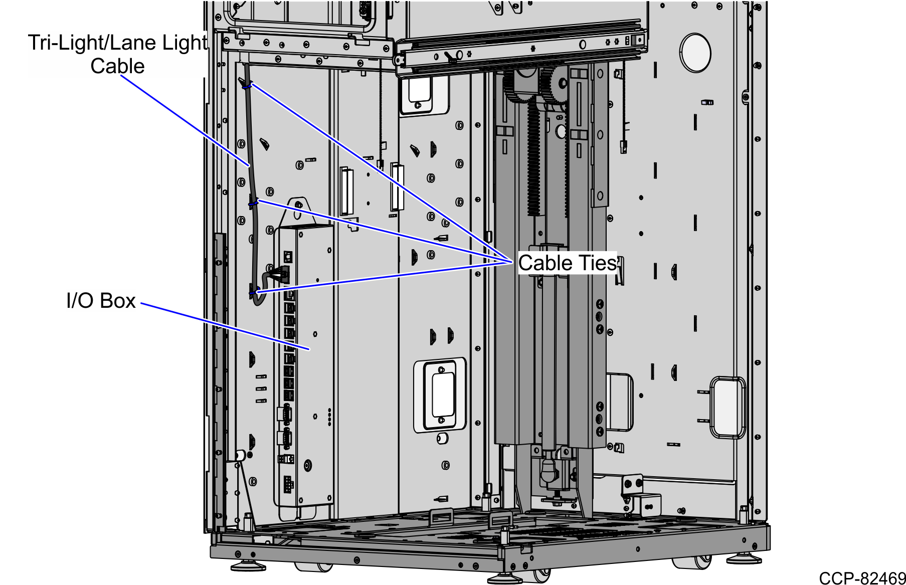
Connect the cable to the Tri-Light/Lane Light port of the I/O Box.
- From the corner cable access hole, route the cable down the Core Cabinet wall and use cable ties to secure the cables on the bridge lances.
- Route the LAN Cable. Depending on the unit configuration, refer to the following:
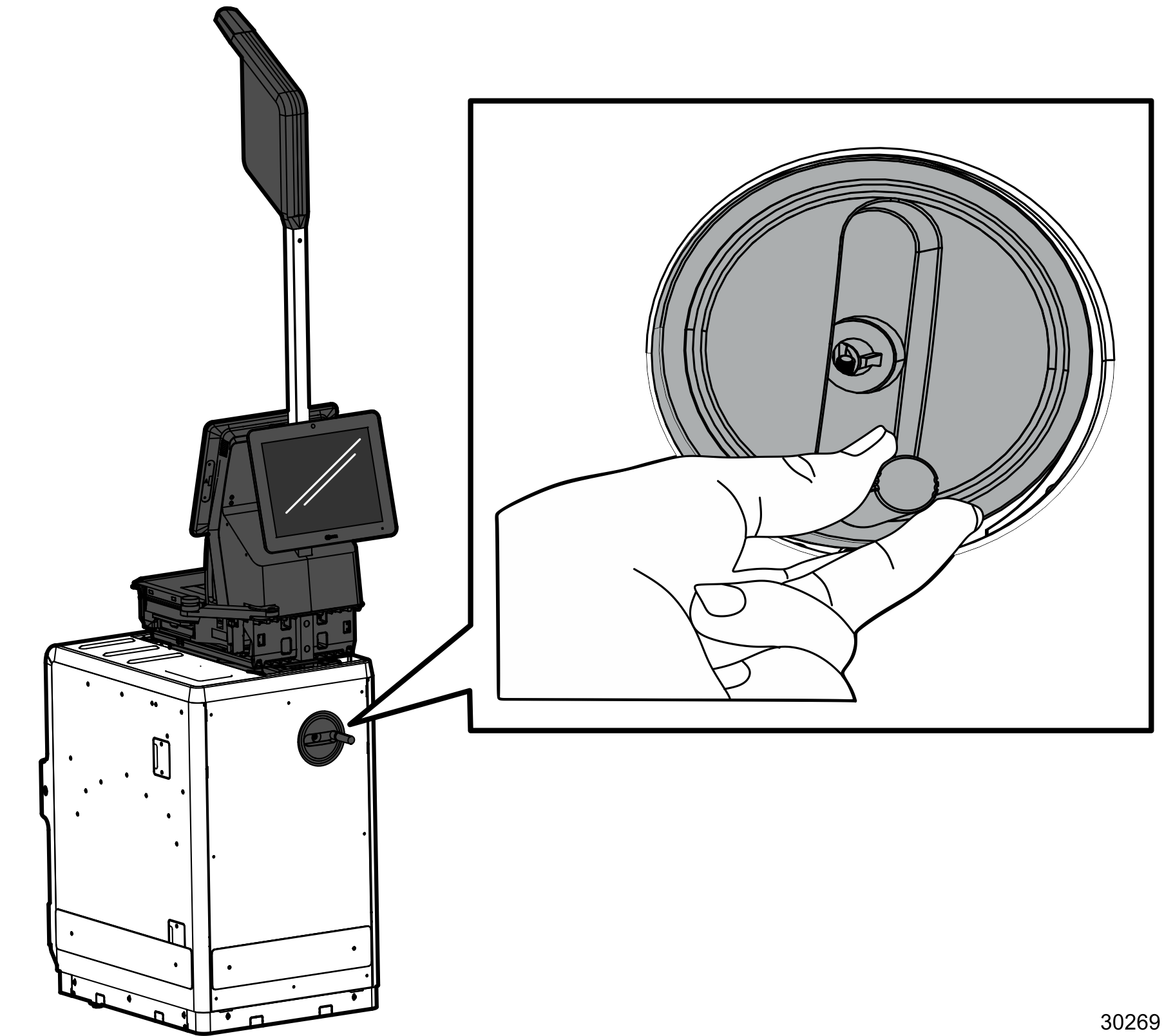
- Lower and raise the Tower Frame by rotating the Conversion Handle to ensure that the cables do not interfere with the movement.
Routing the LAN Cable: No-Bag
To route the LAN Cable, follow these steps:
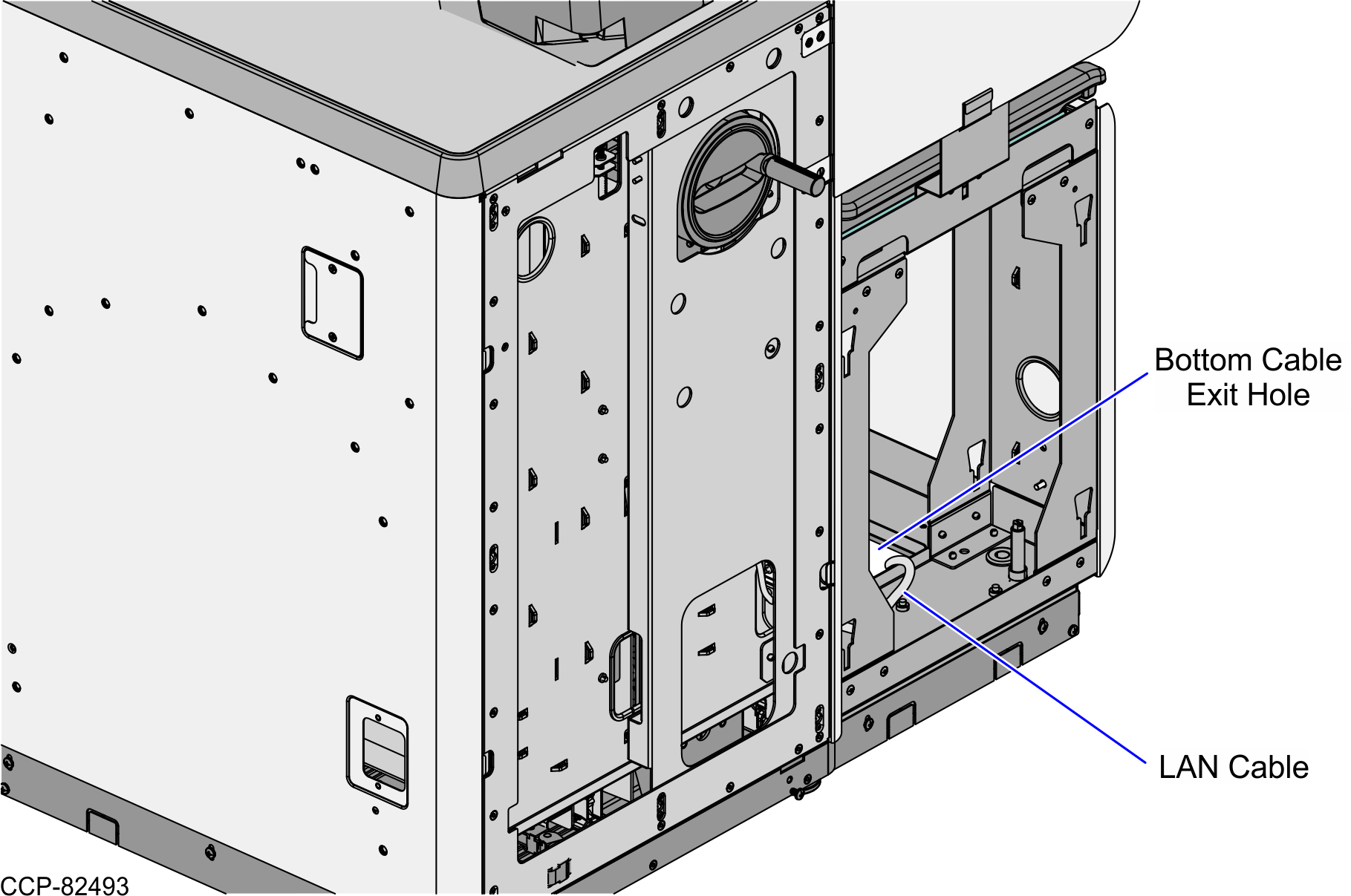
- From the corner cable access hole, route the cable down the Core Cabinet wall and down the bottom exit hole, as shown in the image below.Note
Pass the cable through cable clamps and secure the cable on the bridge lances using cable ties.
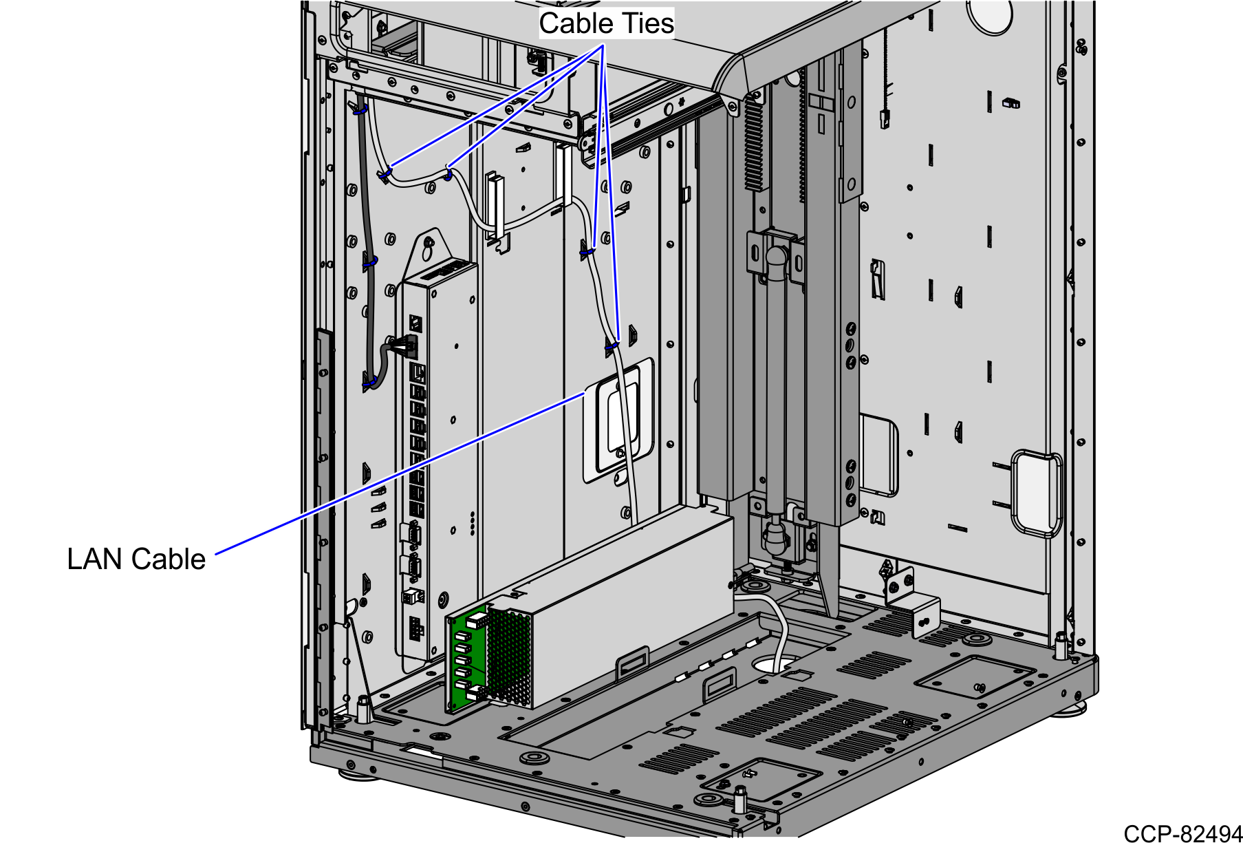
- Connect the cable to the PoE Switch.
Routing the LAN Cable: Left-Hand Unit
To route the LAN Cable, follow these steps:
- From the corner cable access hole, route the cable down the Core Cabinet wall and through the cable access hole, as shown in the image below.Note
Pass the cable through cable clamps and secure the cable on the bridge lances using cable ties.
- Continue to route the cable into Bagwell through the left side exit hole and out through the bottom cable exit hole of the Bagwell.
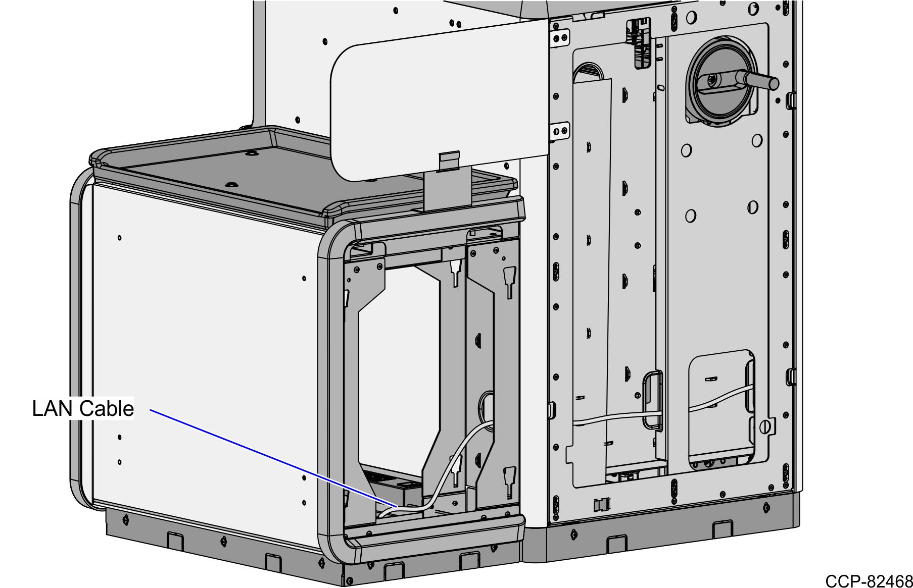
- Connect the cable to the PoE Switch.
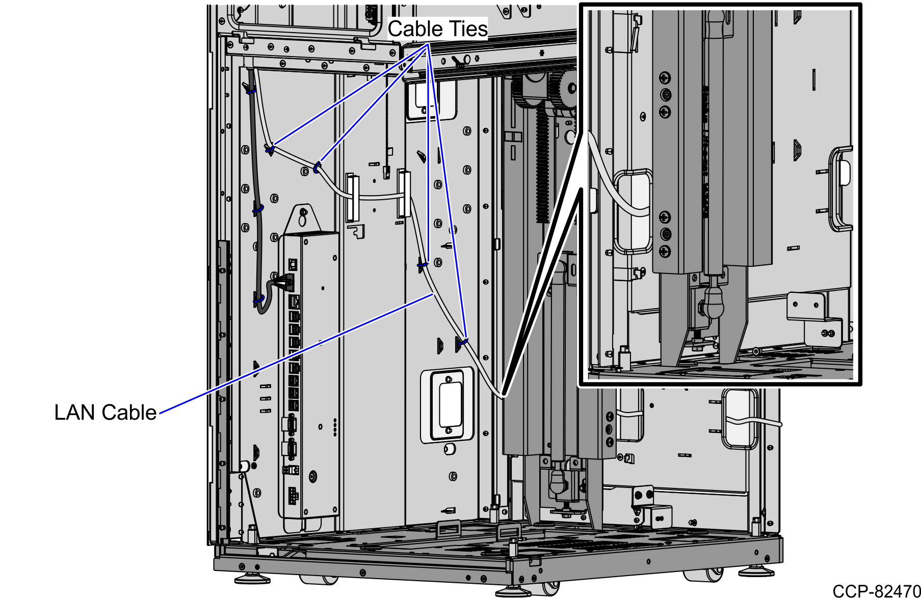
Routing the LAN Cable: Right-Hand Unit
To route the LAN Cable, follow these steps:
- From the corner cable access hole, route the cable down the Core Cabinet wall and through the right cable exit hole, as shown in the image below.Note
Pass the cable through cable clamps and secure the cable on the bridge lances using cable ties.
- Continue to route the cable to the Bagwell and out through the bottom cable exit hole.
- Connect the cable to the PoE Switch.
