Routing the Cables: 7360 R6-C Full Function (Fixed)
To route the Tri-Light/Lane Light Cable and LAN Cable in the Full Function (Fixed) unit, follow these steps:
- Do the following:
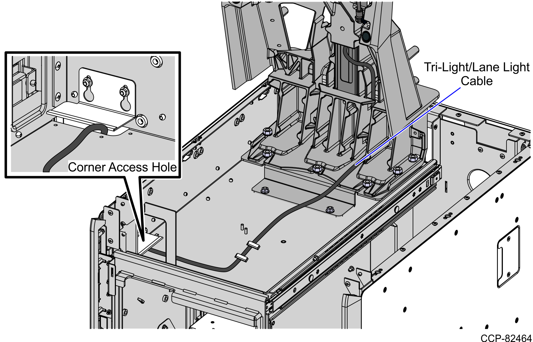
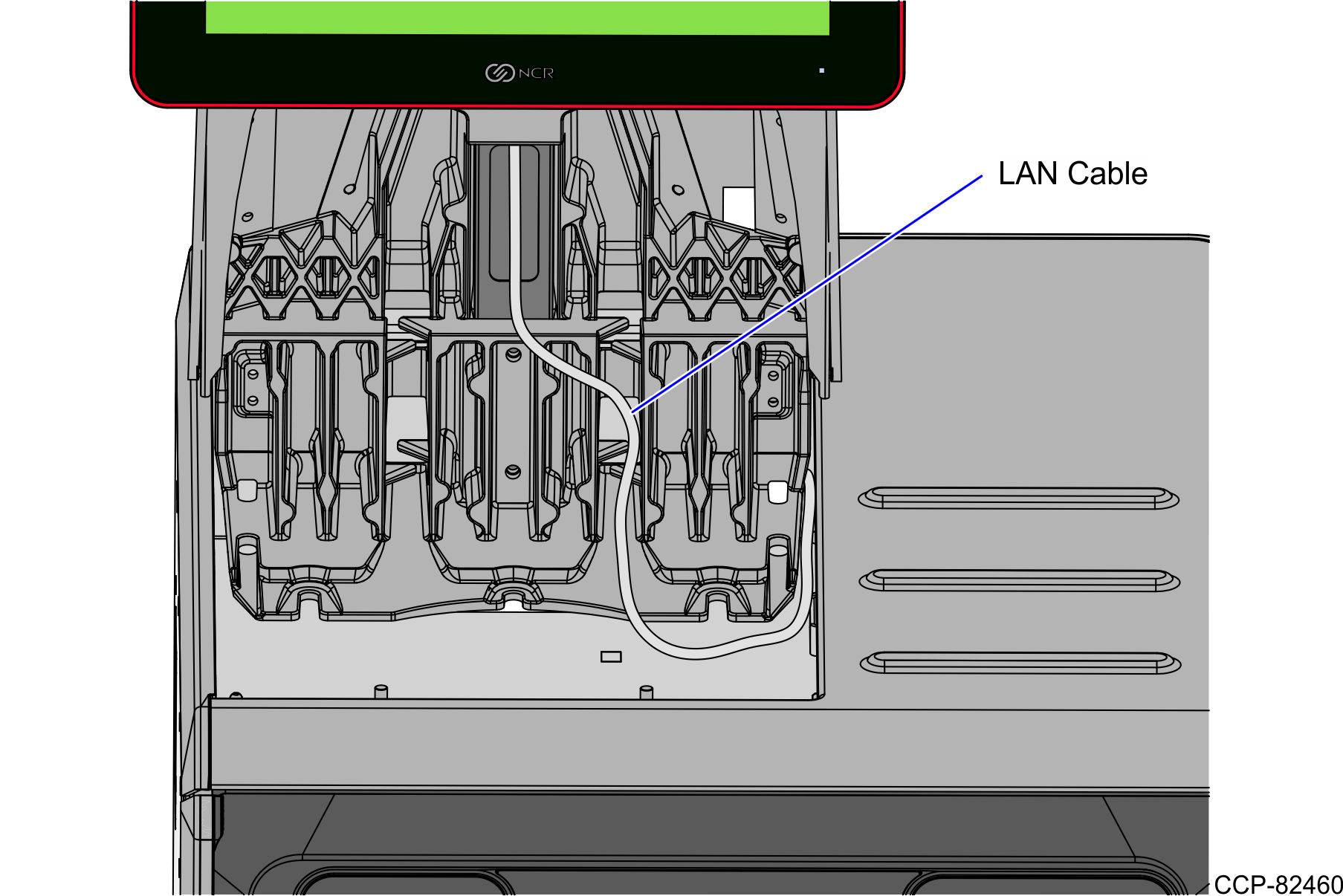
- From the Tower Frame pole duct, route the Tri-Light/Lane Light Cable through the built-in hooks inside the Tower Frame.
- Route the cable down the Scanner Bucket floor. Use cable ties to secure the cable on the bridge lances.
- Secure the cable to the anchor using a cable tie.
- Route the Tri-Light/Lane Light Cable by doing the following:
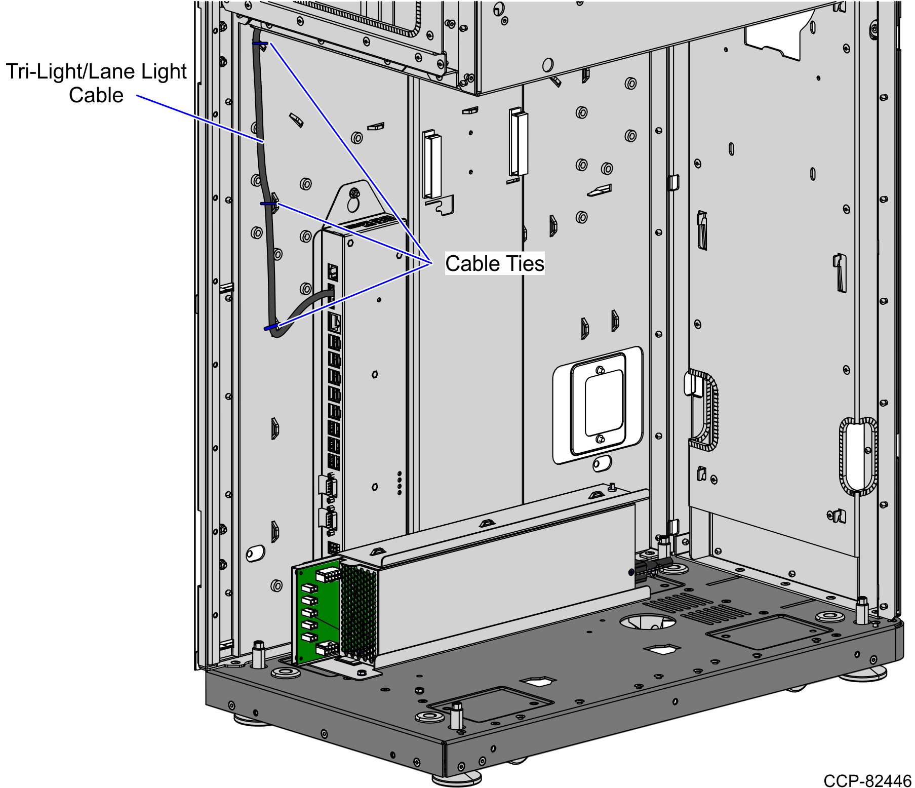
- From the corner cable access hole, route the cable down the Core Cabinet wall and use cable ties to secure the cables on the bridge lances.
- Connect the cable to the Tri-Light/Lane Light port of the I/O Box.
- Route the LAN Cable. Depending on the configuration, refer to the following:
Routing the LAN Cable: No-Bag Unit
To route the LAN Cable, follow these steps:
- Do the following:
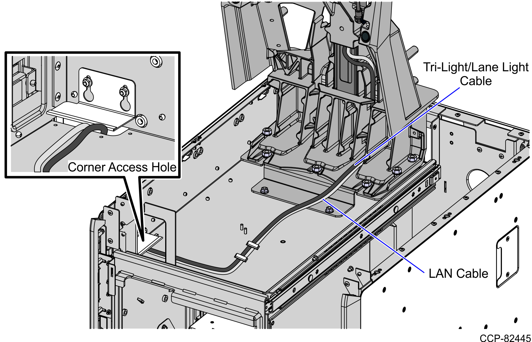
- From the Tower Frame pole duct, route the cable down through the built-in hooks inside the Tower Frame.
- Route the cable down the Scanner Bucket floor. Use cable ties to secure the cable on the bridge lances.
- Secure the cables to the anchor using a cable tie.
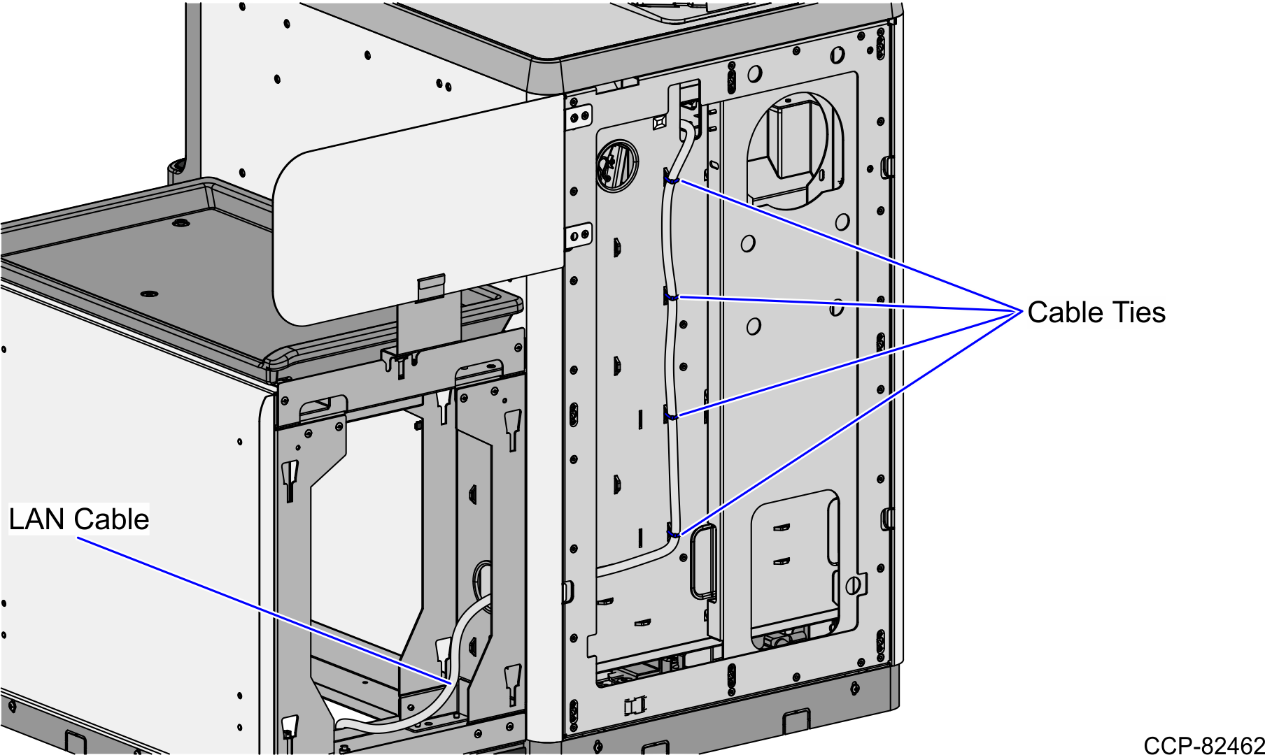
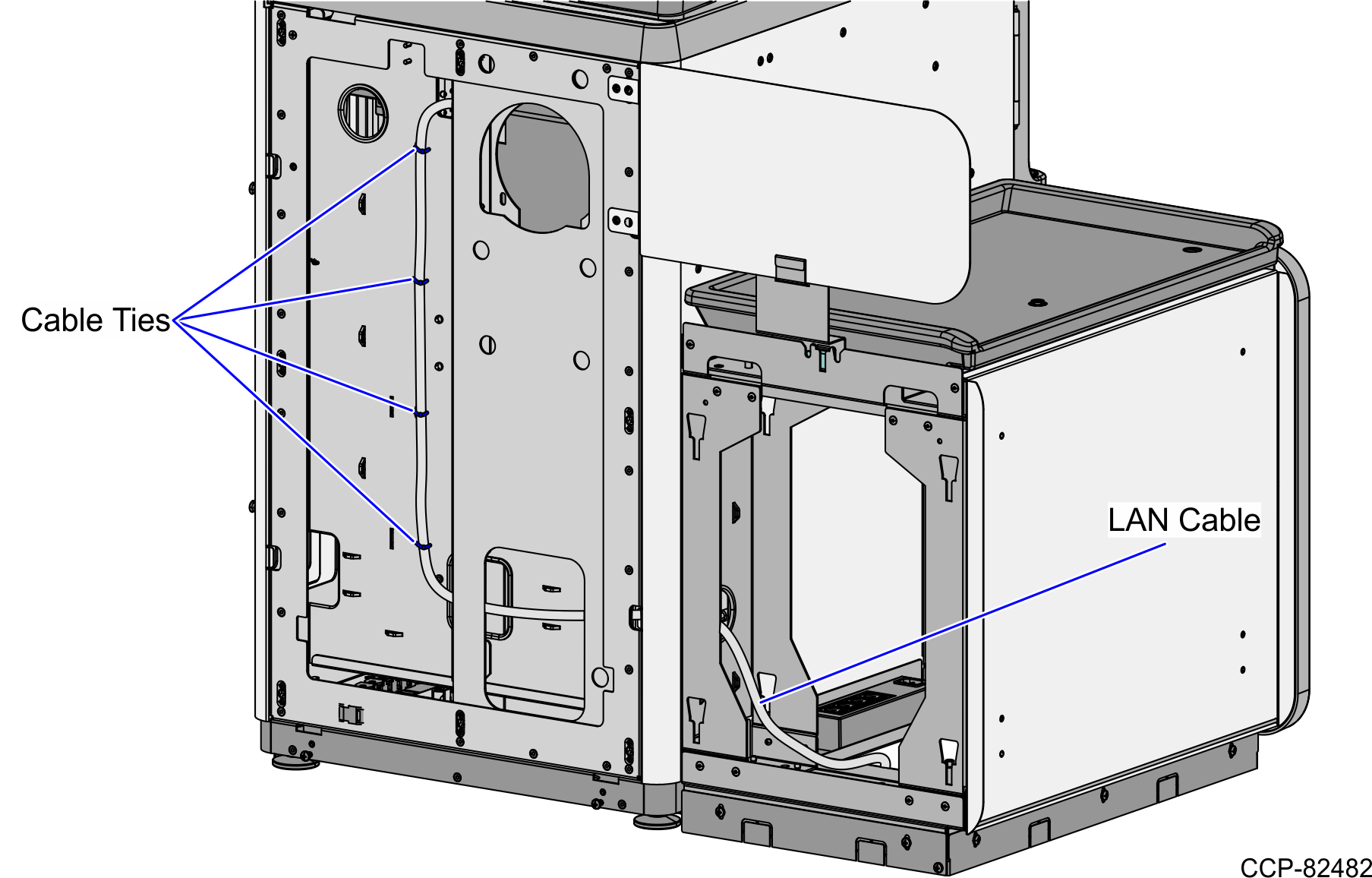
- From the corner cable access hole, route the cable down the Core Cabinet wall and down the bottom exit hole, as shown in the image below.Note
Pass the cable through cable clamps and secure the cable on the bridge lances using cable ties.
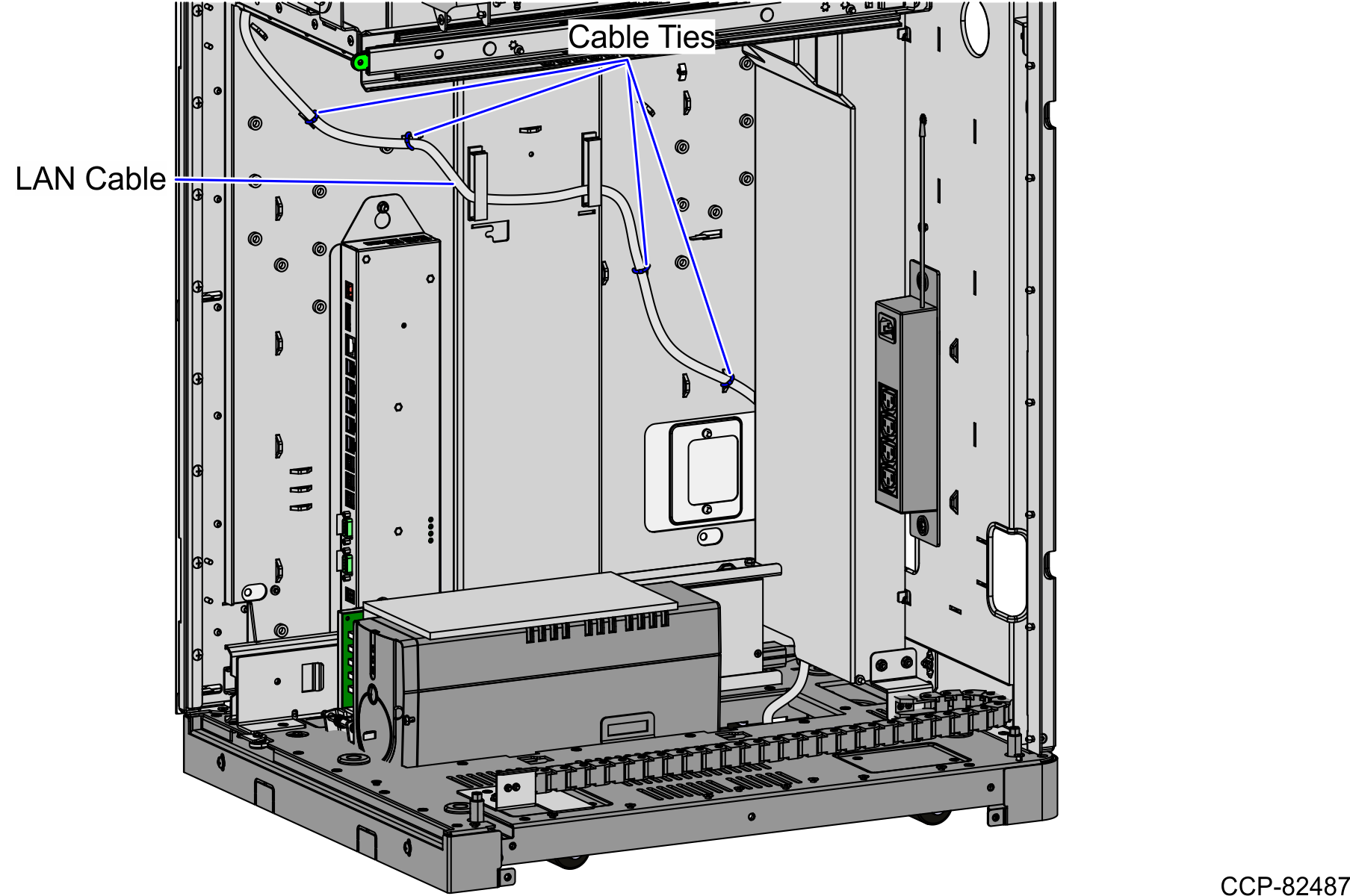
- Connect the cable to the PoE Switch.
Routing the LAN Cable: Left-Hand Unit
To route the LAN Cable, follow these steps:
- From the Tri-Light/Lane Light Pole, route cable down the Scanner Bucket and out through the rear cable access hole.
- From the rear cable access hole, route the cable down the rear of the Core Cabinet and into the Bagwell through the left side cable exit hole. Use cable ties to secure the cable to the lance bridges.
- Continue to route the cable out through the bottom cable exit hole and connect it to the PoE Switch.
Routing the LAN Cable: Right-Hand Unit
To route the LAN Cable, follow these steps:
- From the Tri-Light/Lane Light Pole, route the cable down the Scanner Bucket and out through the rear cable access hole.
- From the rear cable access hole, route the cable down the rear of the Core Cabinet and into the Bagwell through the right side cable exit hole. Use cable ties to secure the cable to the lance bridges.
- Continue to route the cable out through the bottom cable exit hole and connect it to the PoE Switch.
