Installing New Bagwell
To install a new 1-Bag Bagwell, follow these steps:
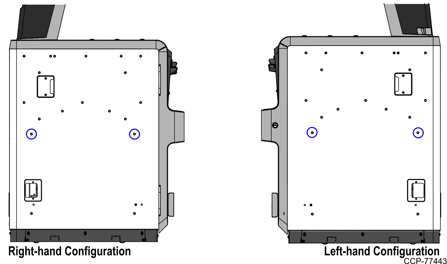
If changing the Bagwell orientation (Left-Hand or Right-Hand), ensure that the orientation is changed before installing the new Bagwell to the Core.
- If installed, remove the following from the Core:
- Back Panel
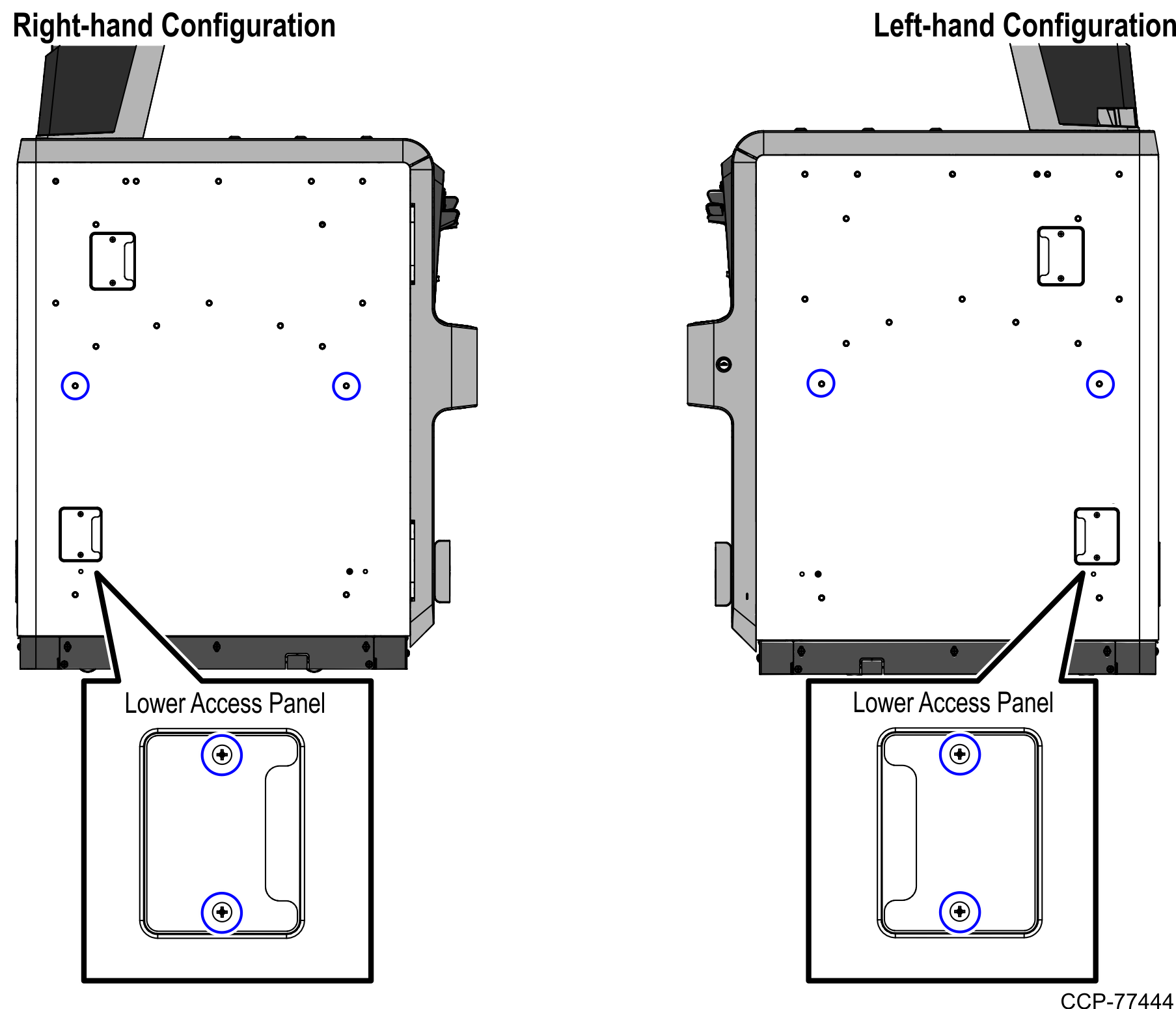
- Lower Access Panel (2 screws) from the side of the Core where the new Bagwell will be installed
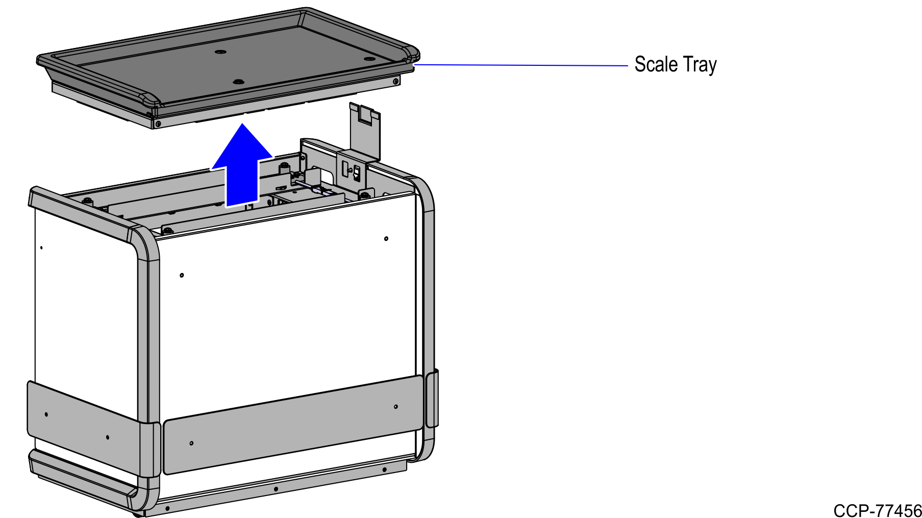
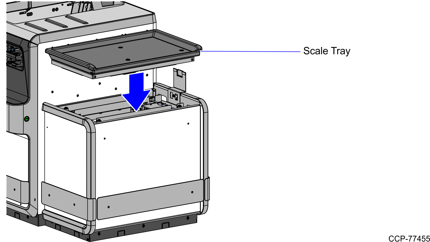
- Lift and remove the Scale Tray from the Bagwell.
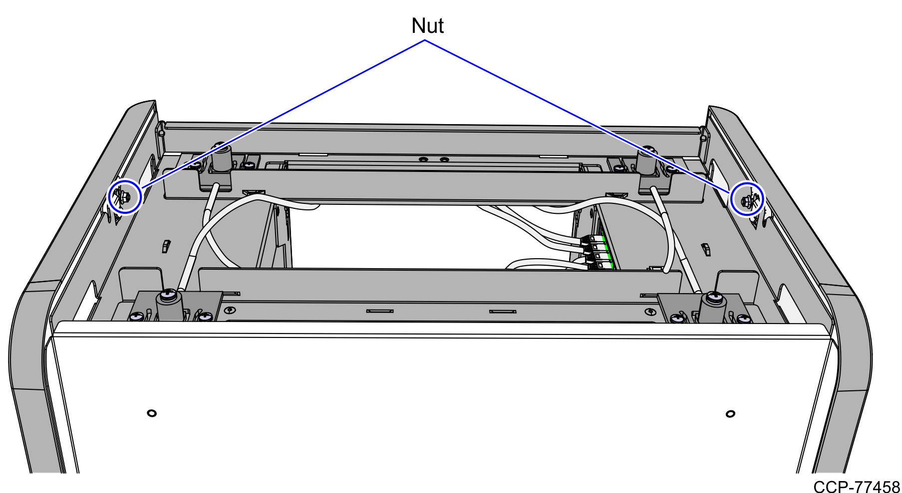
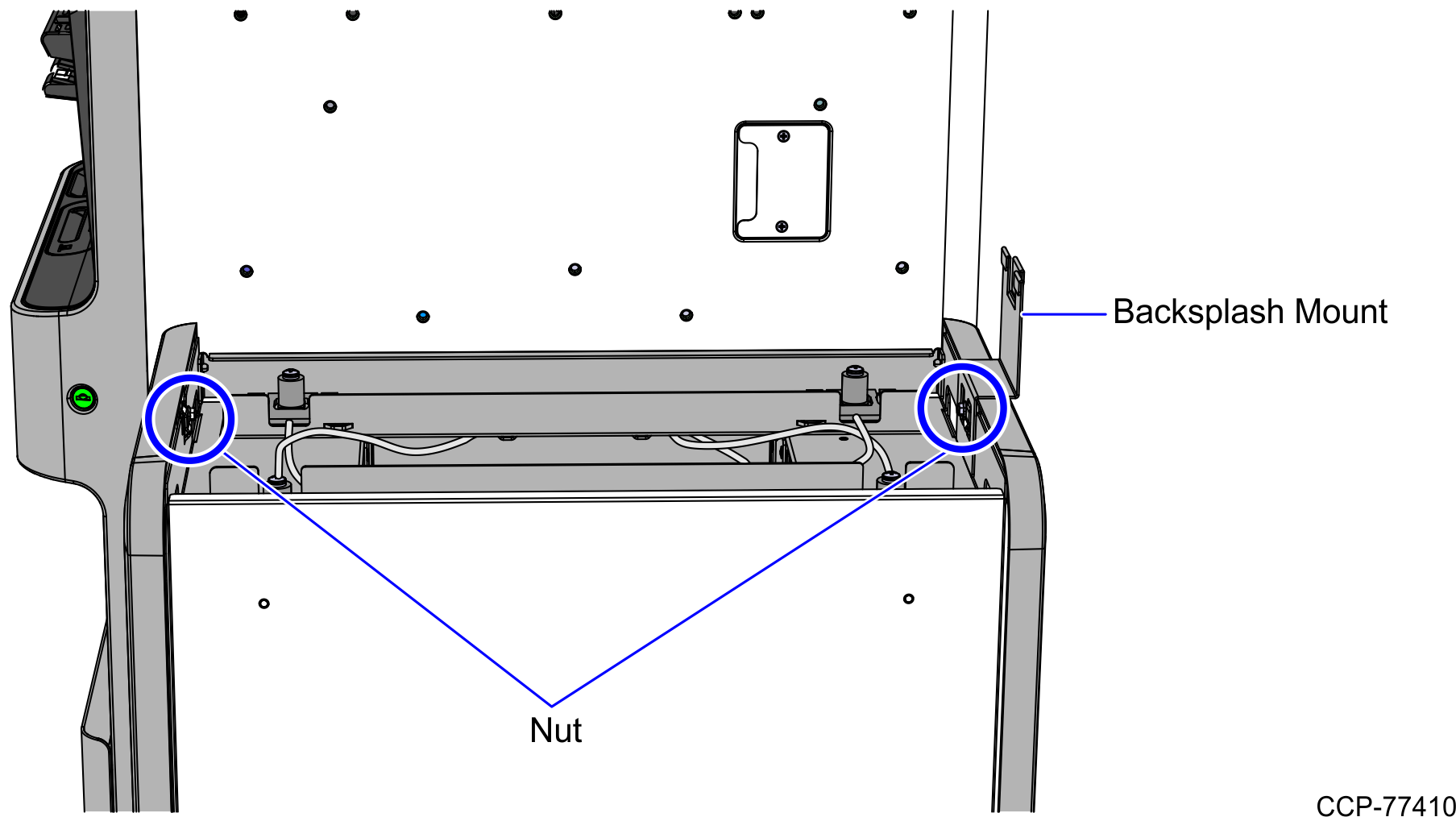
- Loosen two (2) nuts that secure the front and back color panels to the frame, as shown in the image below.
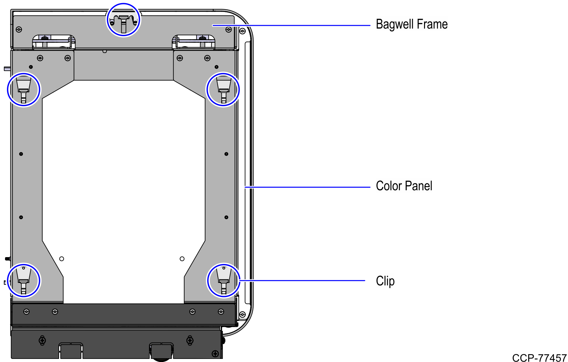
- Remove the front and back color panels by pulling it up until it unclips from the Bagwell Frame.
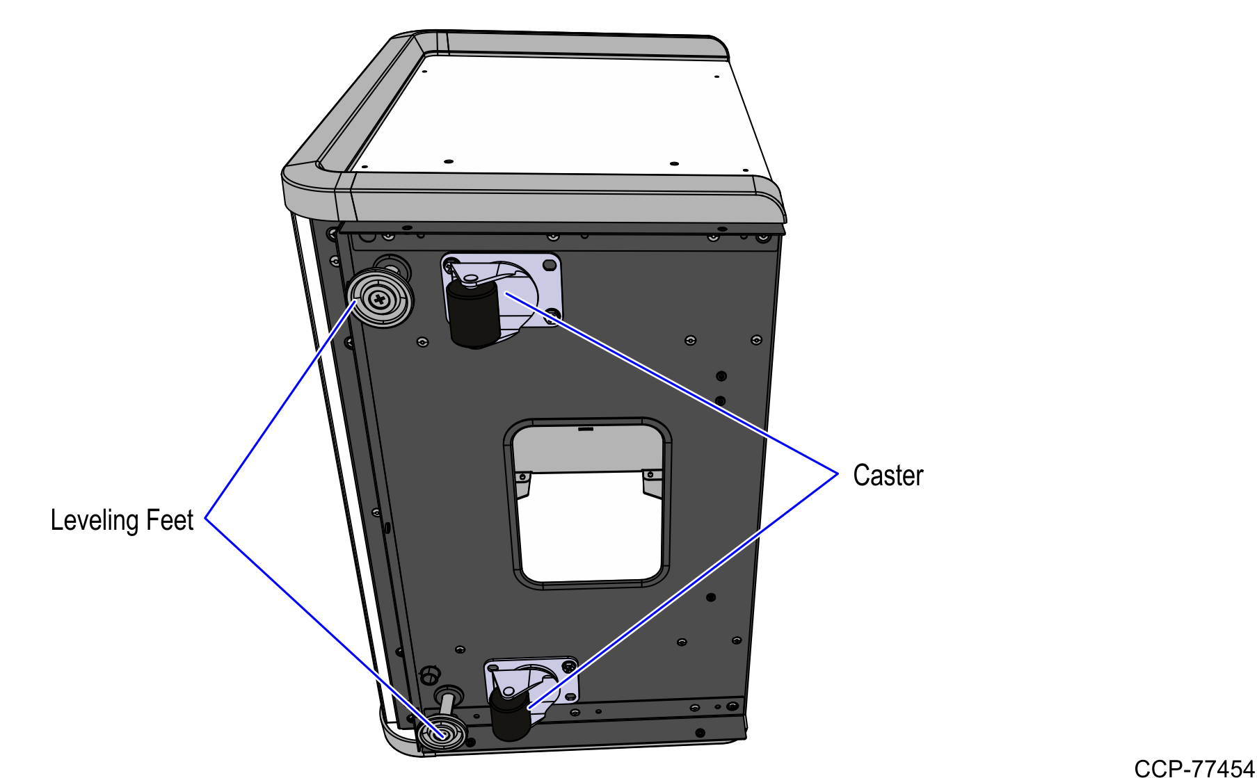
- Lower all Bagwell Leveling Feet slightly beyond height of the casters. This will assist in lining up the Core and Bagwell mounting holes.
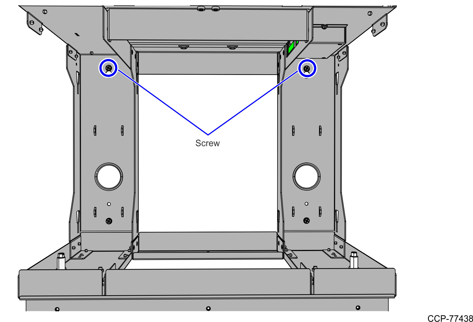
- If not already present, partially thread two (2) screws on the Bagwell side of the Core as shown. Leave approximately ¼ inch of threads exposed.
- Mate the new Bagwell to the Core by lifting the Bagwellframe up and over the partially threaded screws.Note
Ensure that the two (2) center key holes on the Bagwell Side Support are used.
- Tighten the two (2) screws.
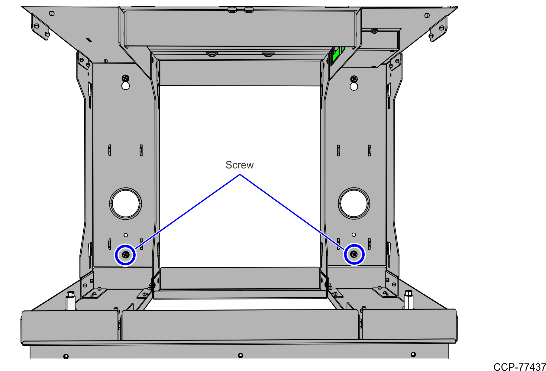
- Install the two (2) lower screws to secure the Bagwell to the Core.
- Route the cables through the access hole:
Bagwell Cable Access Hole
- AC Power In Cable
Core Cable Access Hole
- AC Power Out Cables
- Local Area Network (LAN) Cable
- USB Power Cable
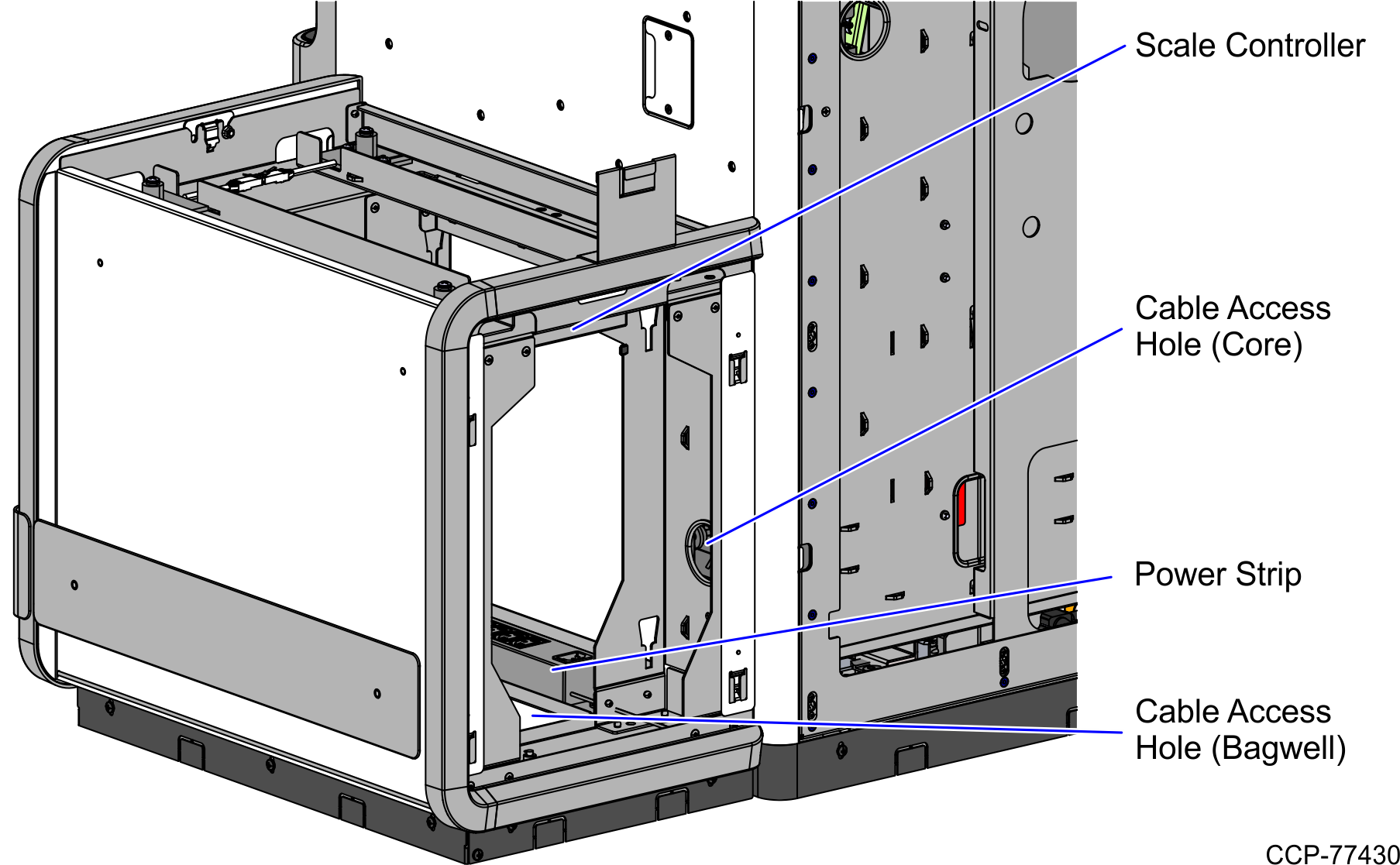
- Connect the cables:
- AC Power In Cable to the Power Strip
- AC Power Out Cables to the Power Strip
- Local Area Network (LAN) Cable to the Customer Interface
- USB Power Cable to the Scale Controller
NoteFor more information, refer to Cable Routing.
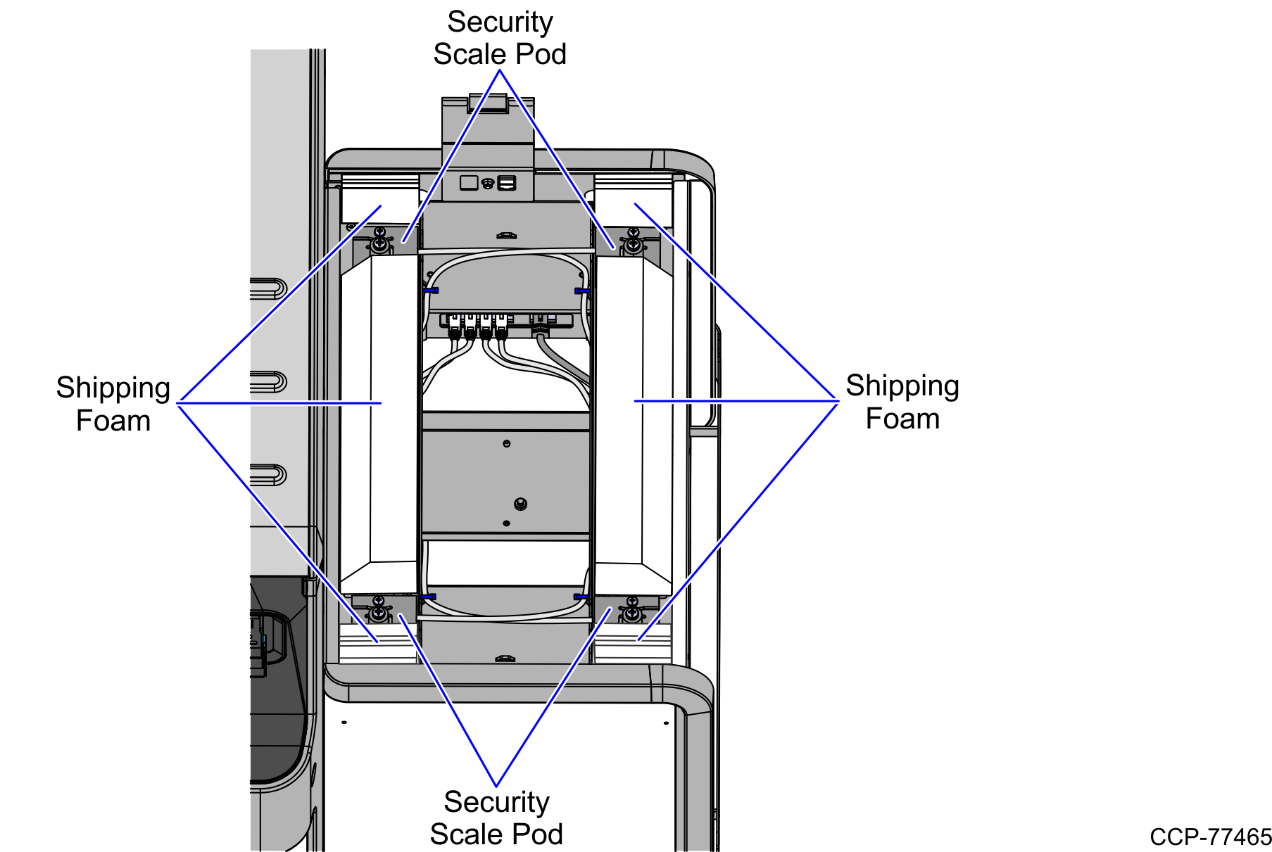
- Remove the shipping foams from the scale pods, as shown in the image below.
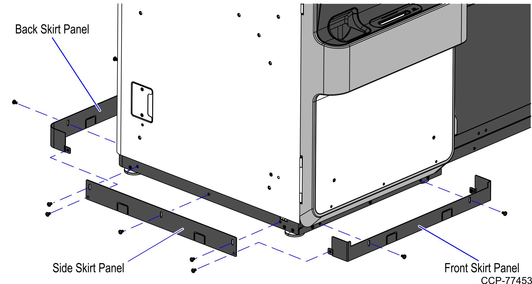
- If not already installed, install the skirt panels on the bottom of the Core.Note
The front and back skirt panels of the Core must be installed before the side skirt panel. Use two screws for each of the front and back panels and five (5) screws for the side panel.
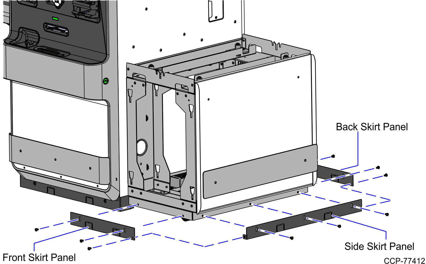
- Install the skirt panels on the bottom of the Bagwell using nine (9) screws.Note
The side skirt panel of the Bagwell must be installed before the front and back skirt panels.
- Reinstall the front and back color panels of the Bagwell by sliding down each panel until it clips into place.
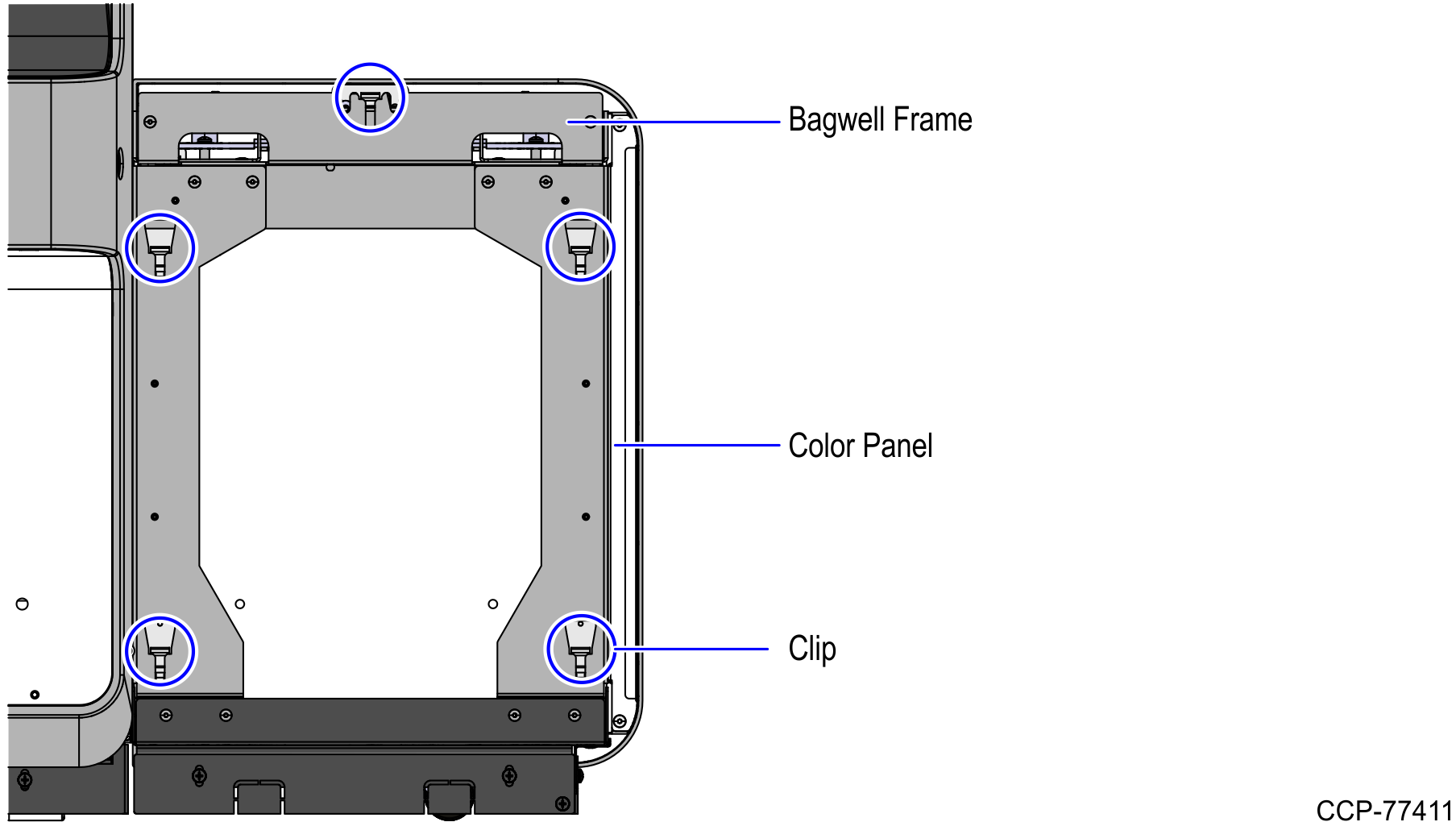
- Secure both color panels and the Backsplash Mount to the frame with two (2) nuts, as shown in the image below.
- Reinstall the Scale Tray.Note
Ensure that the Scale Tray is placed on its correct orientation by placing the side with the raised edge along the Core wall. This prevents items on the tray from making contact with the Core wall which can affect the reported weight.
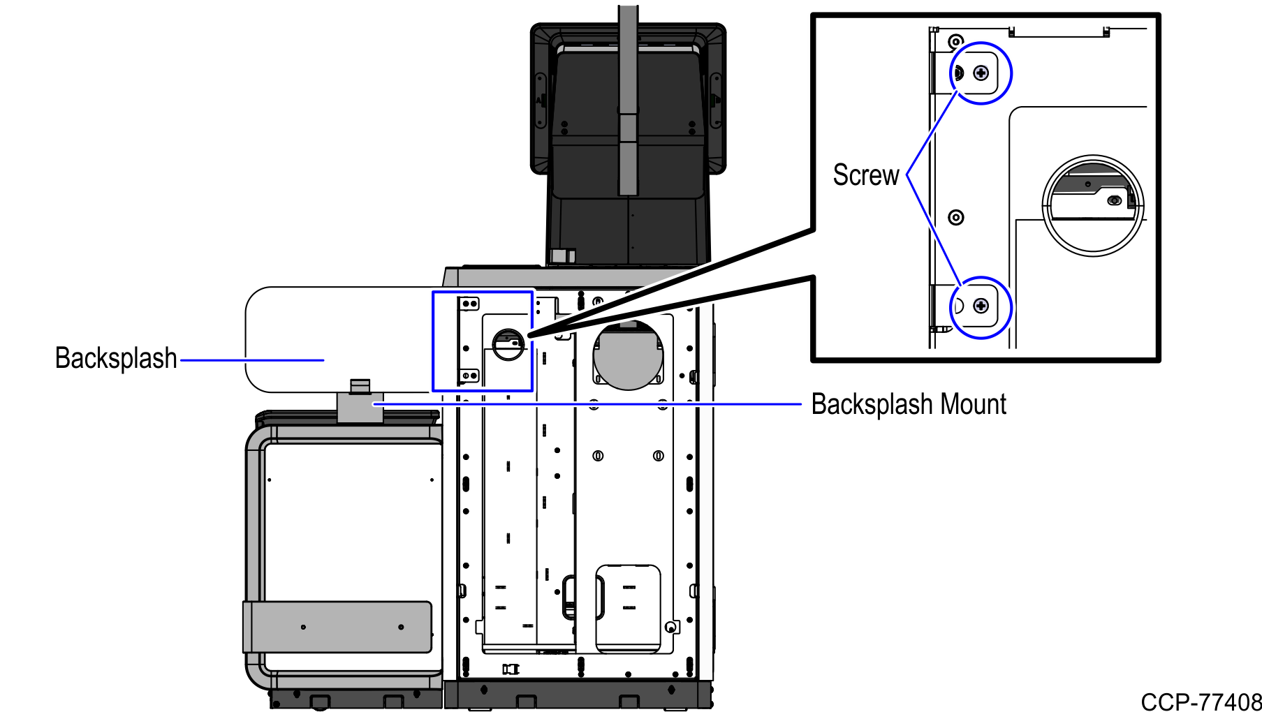
- Install the Backsplash.
- Install the Backsplash onto the Mount.
- Secure the Backsplash to the back of the Core using two (2) screws.
- Reinstall the back panel of the Core.
- Level the Checkstand. For more information, refer to NCR Fastlane SelfServ™ Checkout (7360) Hardware Installation Guide (B005-0000-2377).