Routing the PIN Pad cable through the PIN Pad Arm
To route the PIN Pad cable, follow these steps:
- Access the Retail I/O Box. For more information, refer to Accessing the Retail I/O Box.
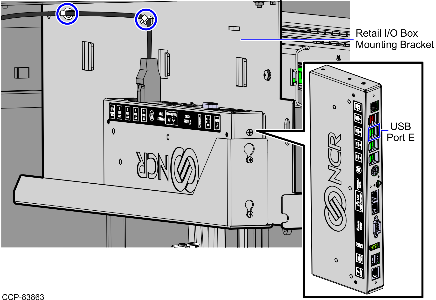
- Connect the PIN Pad device cable to the 12V powered USB port E of the Retail I/O Box.
- Secure the PIN Pad device cable on the Retail I/O Box Mounting Bracket using cable ties, as shown in the image below.
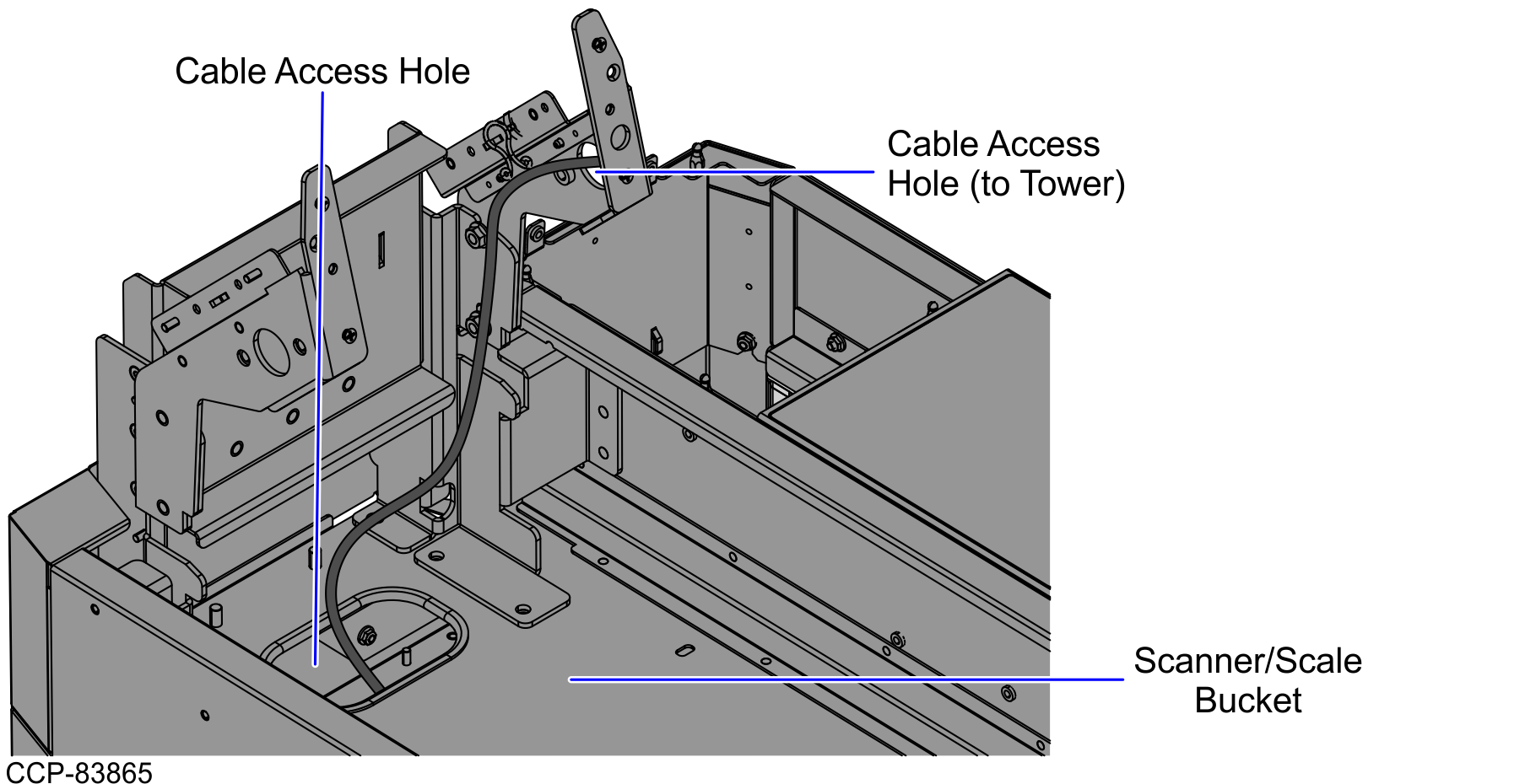
- Route the device cable up through the cable access hole going up to the and Scanner/Scale Bucket and Tower Cabinet, as shown in the image below.
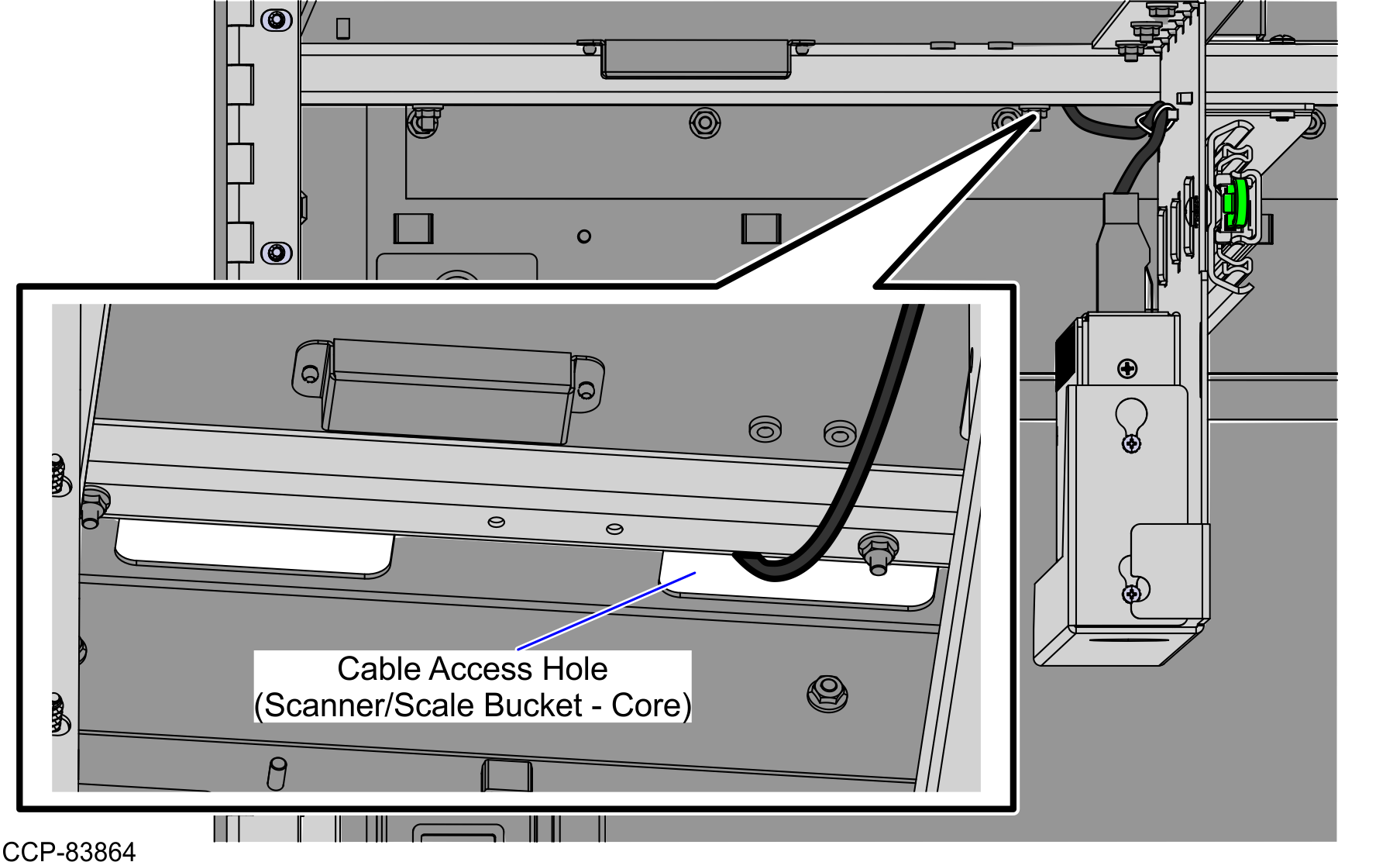
- From the cable access hole on the Scanner/Scale Bucket, route the PIN Pad device cable up to the cable access hole on the Tower Cabinet , as shown in the image below.
- Do the following:
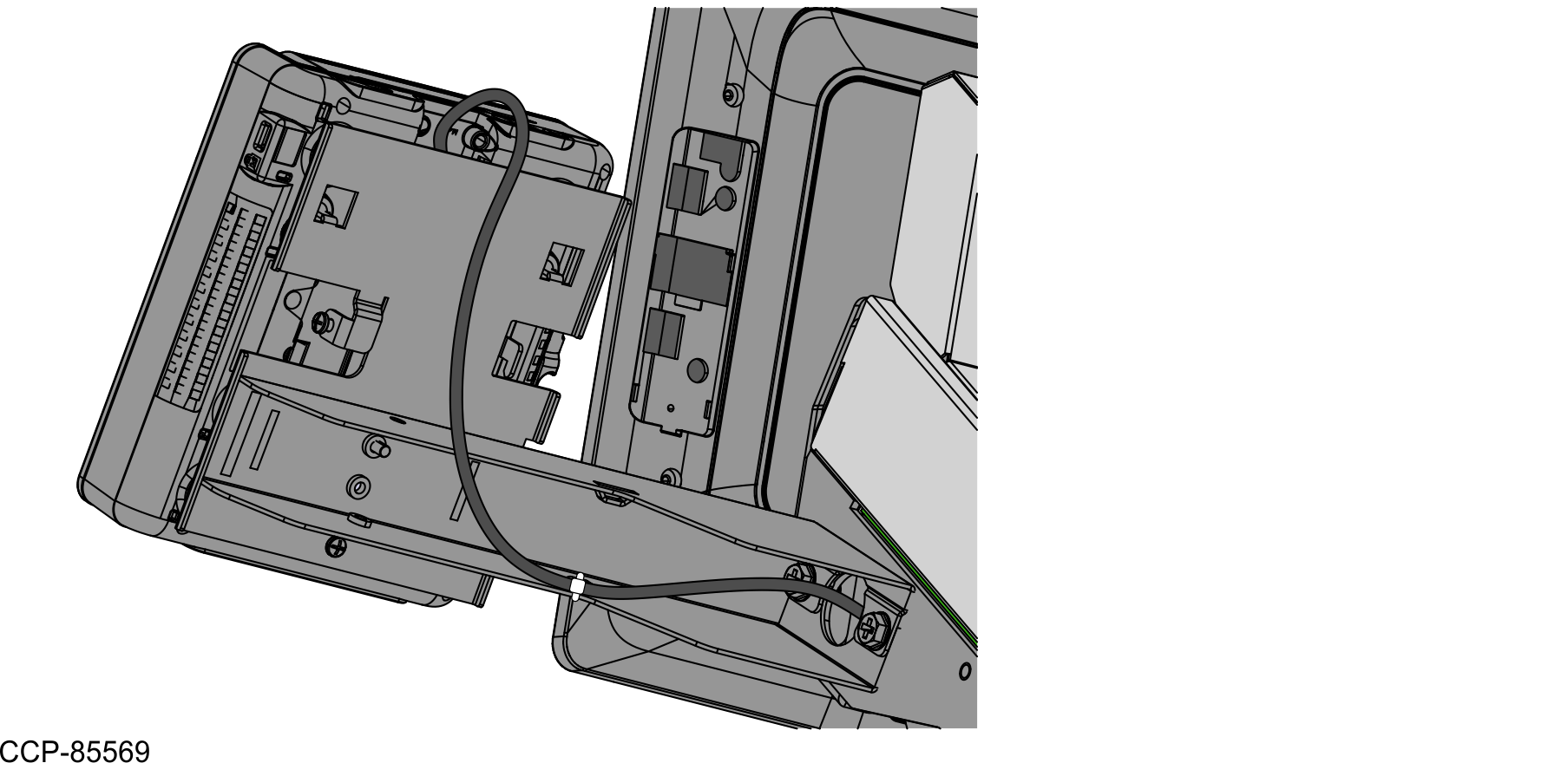
- Route and secure the PIN Pad device cable on the lance bridge at the back of the PIN Pad Arm.
- Connect the PIN Pad device cable to the Ingenico ISC250 PIN Pad, as shown in the image below.