Routing Security Scale Controller Cable: 7371 Full Function Self-Checkout
Depending on the orientation of the unit, refer to the following sections:
The NCR Voyix Self-Checkout units with a Bagging Area (Bagwell) Module can be configured for either Left-hand (LH) orientation or Right-hand (RH) orientation, which refers to the direction customers scan and bag items.
- Left-hand (LH) orientation-Customers scan from left to right.
- Right-hand (RH) orientation-Customers scan from right to left.
The orientation of the unit is determined by the position of the Lower Core (Cabinet) Module in relation to the Bagging Area (Bagwell) Module.
The Left-hand (LH) orientation has the unit positioned on the left side of the Bagwell.
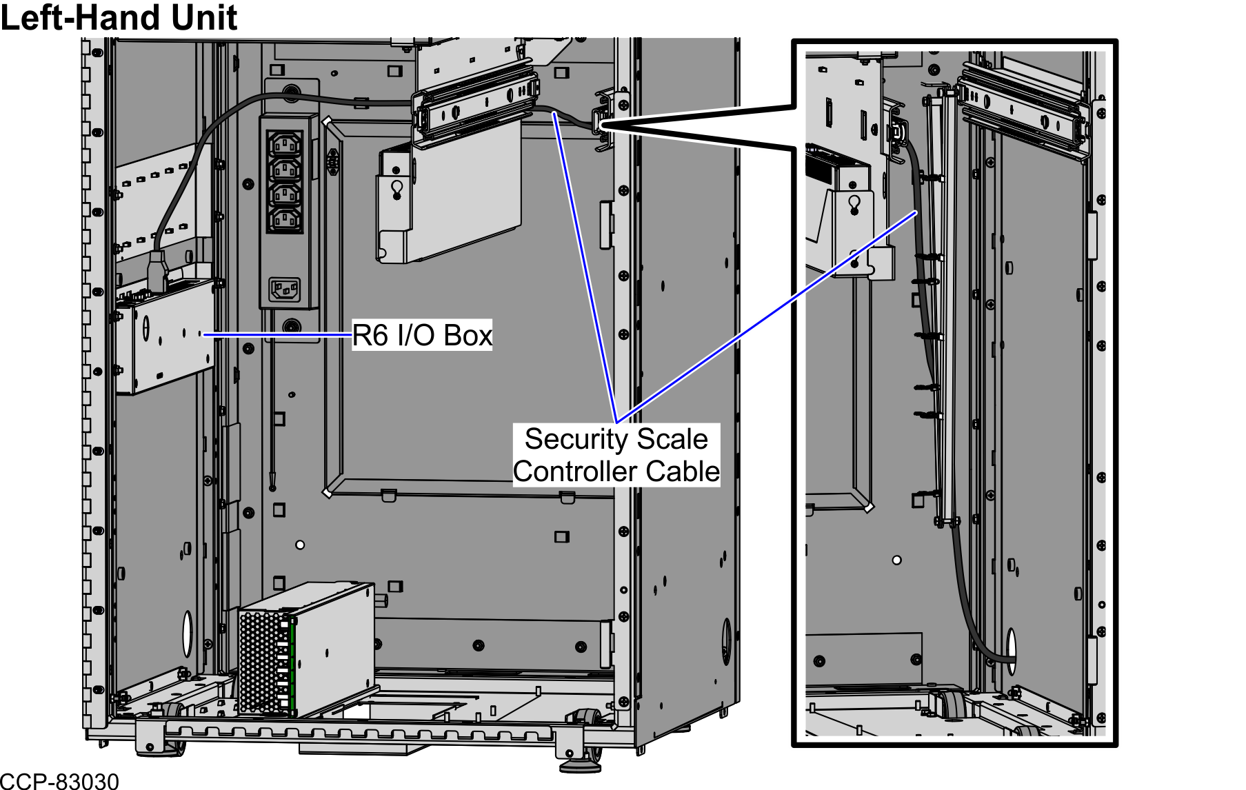
Left-Hand Unit
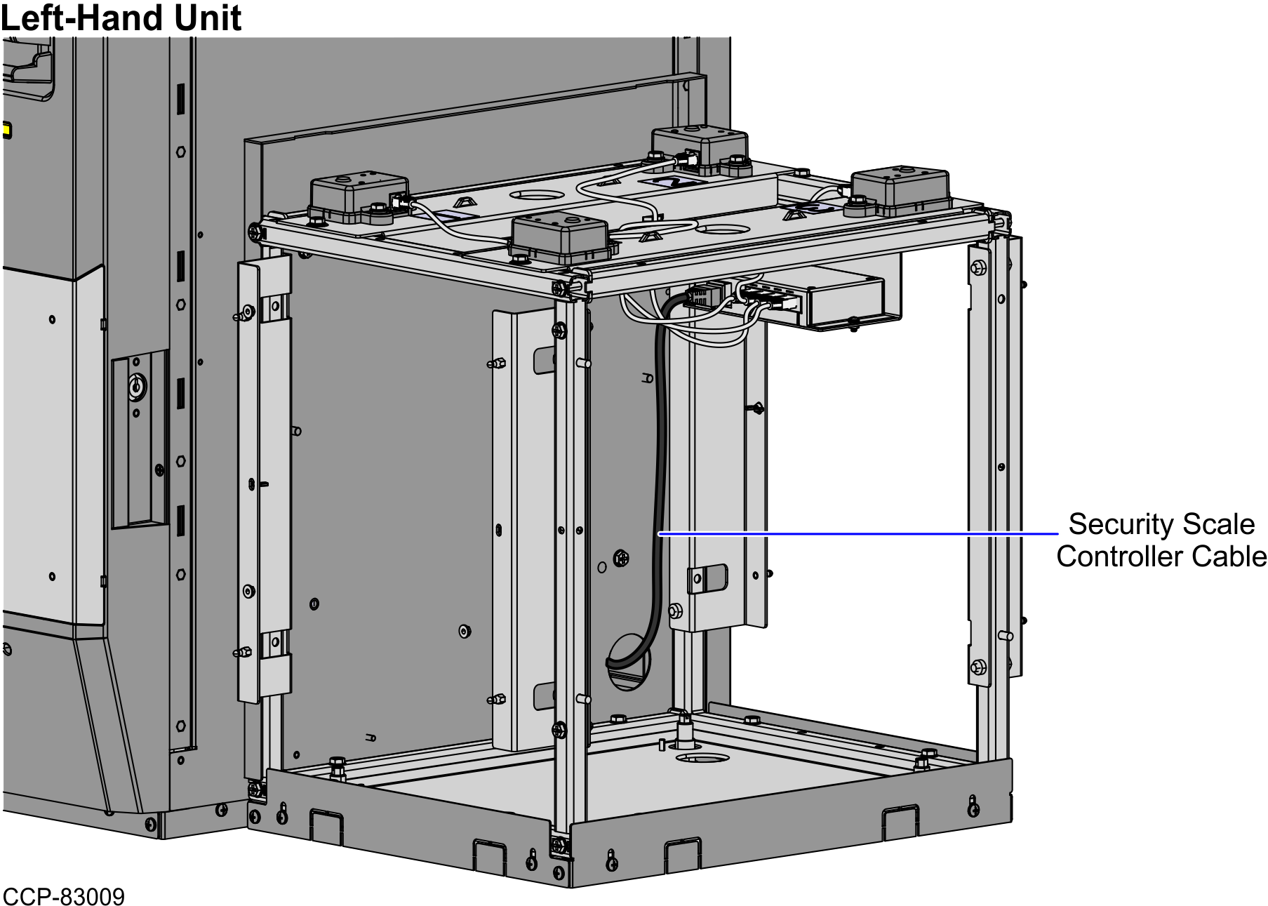
To route the Security Scale Controller Cable in a Left-Hand unit, follow these steps:
- From the Bagwell, route the cable down and through the side cable access hole and into the unit.Note
For illustration purposes, the Bagwell Panel (Fascia End) is not included below to show the cable route.
- Open the Core Cabinet.
- Do the following:
- Rack out the Coin Recycler.
- Rack out the Note Recycler.
- From the side cable access hole, route the cable along the cabinet wall and connect to the R6 I/O Box (Port G).
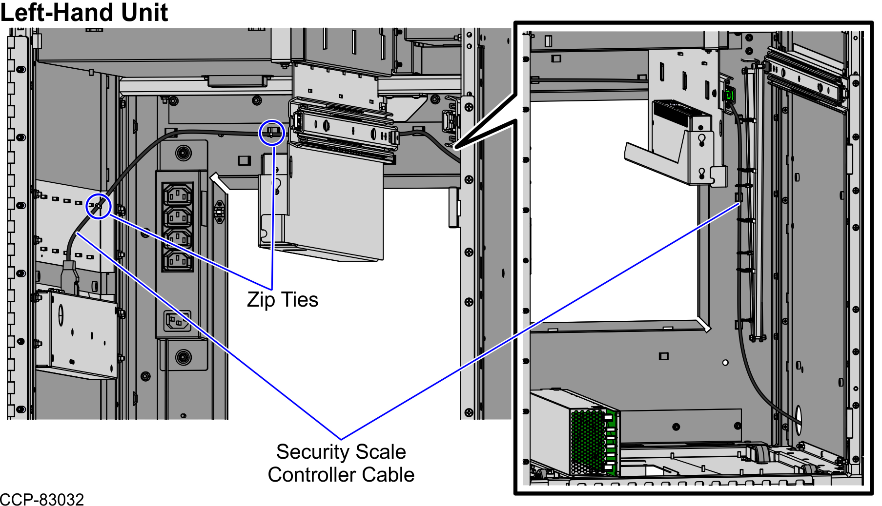
- Tie the cable with the cable bundle along the cabinet wall using zip ties, as shown in the image below.Note
Ensure that there is enough cable slack to avoid cables from being stretched during installation or removal procedures.
TipYou may open the Back Panel to easily secure the cable with the cable bundle using zip ties.
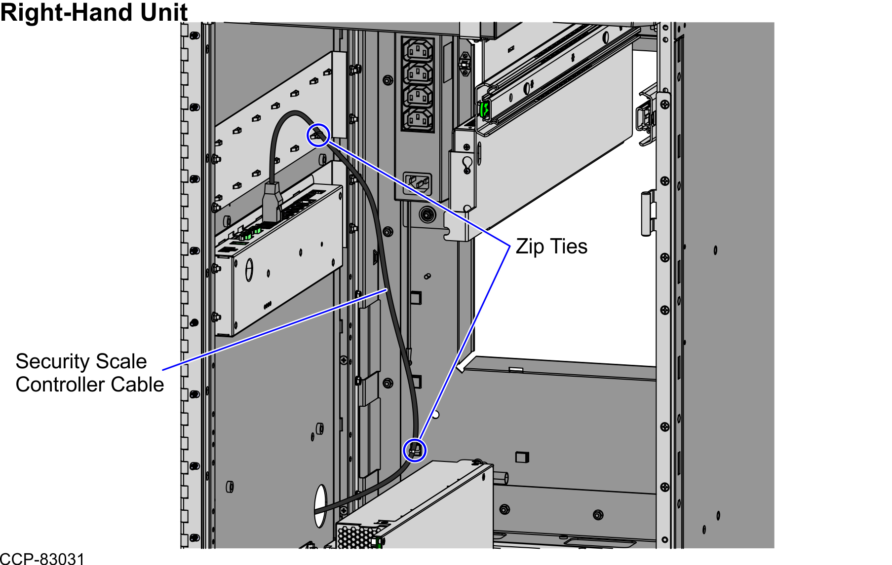
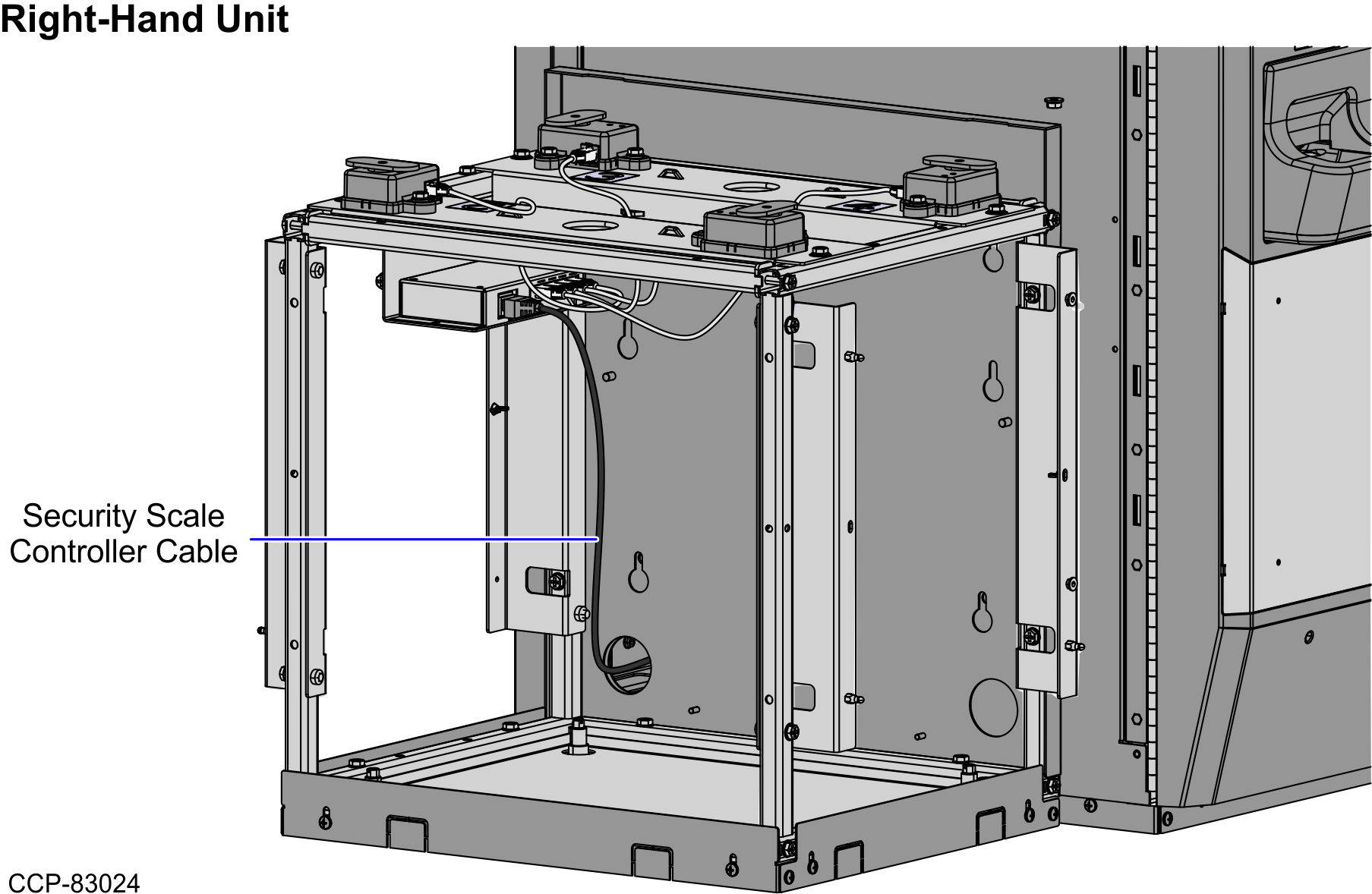
Right-Hand Unit
To route the Security Scale Controller Cable in a Right-Hand unit, follow these steps:
- From the Bagwell, route the cable down and through the side cable access hole and into the unit.Note
For illustration purposes, the Bagwell Panel (Fascia End) is not included below to show the cable route.
- Open the Core Cabinet.
- Rack out the Coin Recycler.
- From the side cable access hole, route the cable along the cable bundle and connect to the R6 I/O Box (Port G).
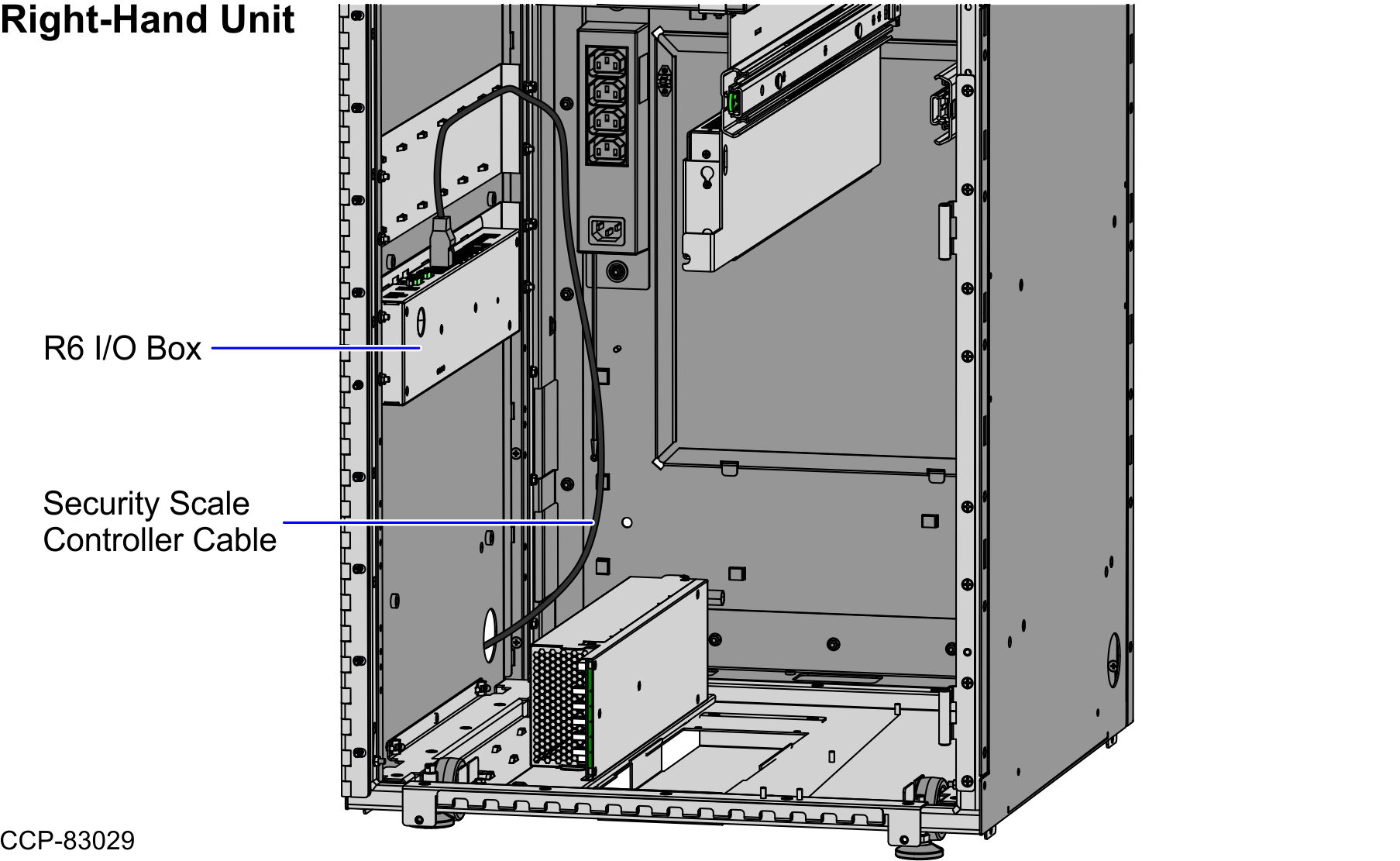
- Tie the cable with the cable bundle using zip ties, as shown in the image below.Note
Ensure that there is enough cable slack to avoid cables from being stretched during installation or removal procedures.
TipYou may open the Back Panel to easily secure the cable with the cable bundle using zip ties.