Routing USB-to-Serial Adapter Cable
To route the USB-to-Serial Adapter Cable, follow these steps:
- Shut down the NCR SelfServ™ Checkout (7707) R6-Japan software and hardware systems.
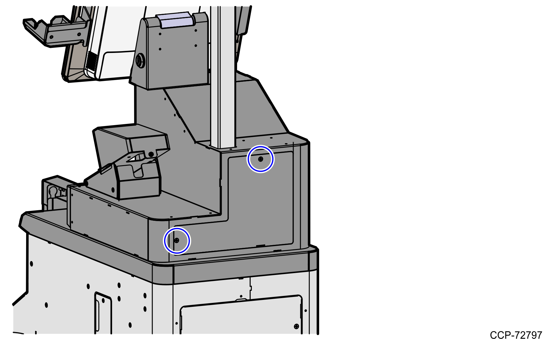
- Detach the back panel from the Tower Frame by removing two (2) screws.
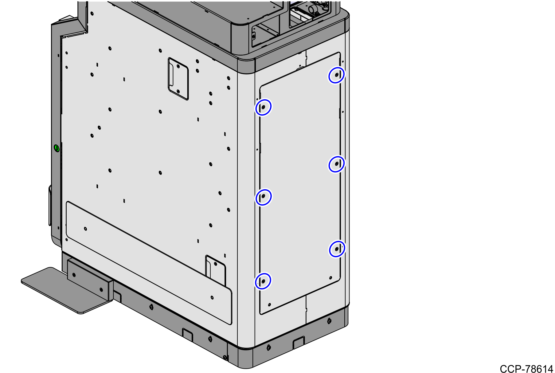
- Detach the back panel of the Lower Core (Cabinet) Module by removing six (6) screws to access the devices and cable routing.
- Disconnect the currency device connector from the KIO board by doing the following:
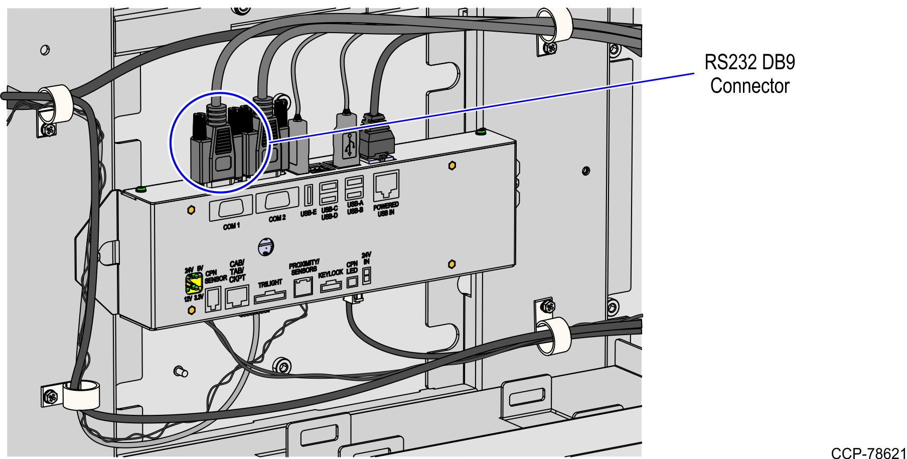
- Access the KIO Board.
- Disconnect the RS232 DB9 connector from the COM1 port of the KIO Board, as shown in the image below.
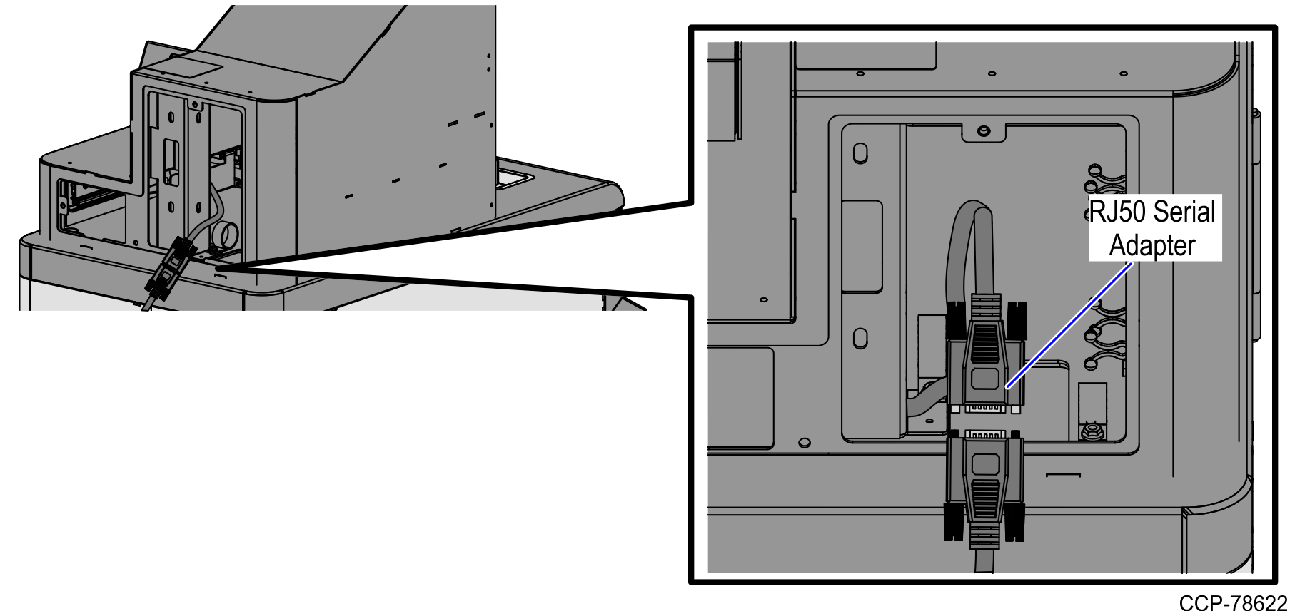
NoteFor units where the currency device cable is connected to the RJ50 serial adapter of the NCR Terminal Display, disconnect the cable as shown in the image below.
WarningEnsure that the system is turned off before disconnecting or connecting cables to avoid damaging the internal chip of the NCR Terminal Display and making the adapter unusable.
- Remove the cable from the P-loops until the cable reaches the Upper Enclosure assembly.
- Unlock the Tower frame from the back using a key.
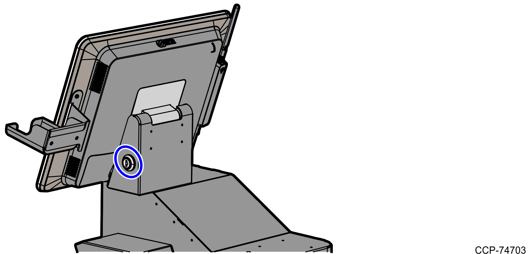
- Raise the NCR Terminal Display.
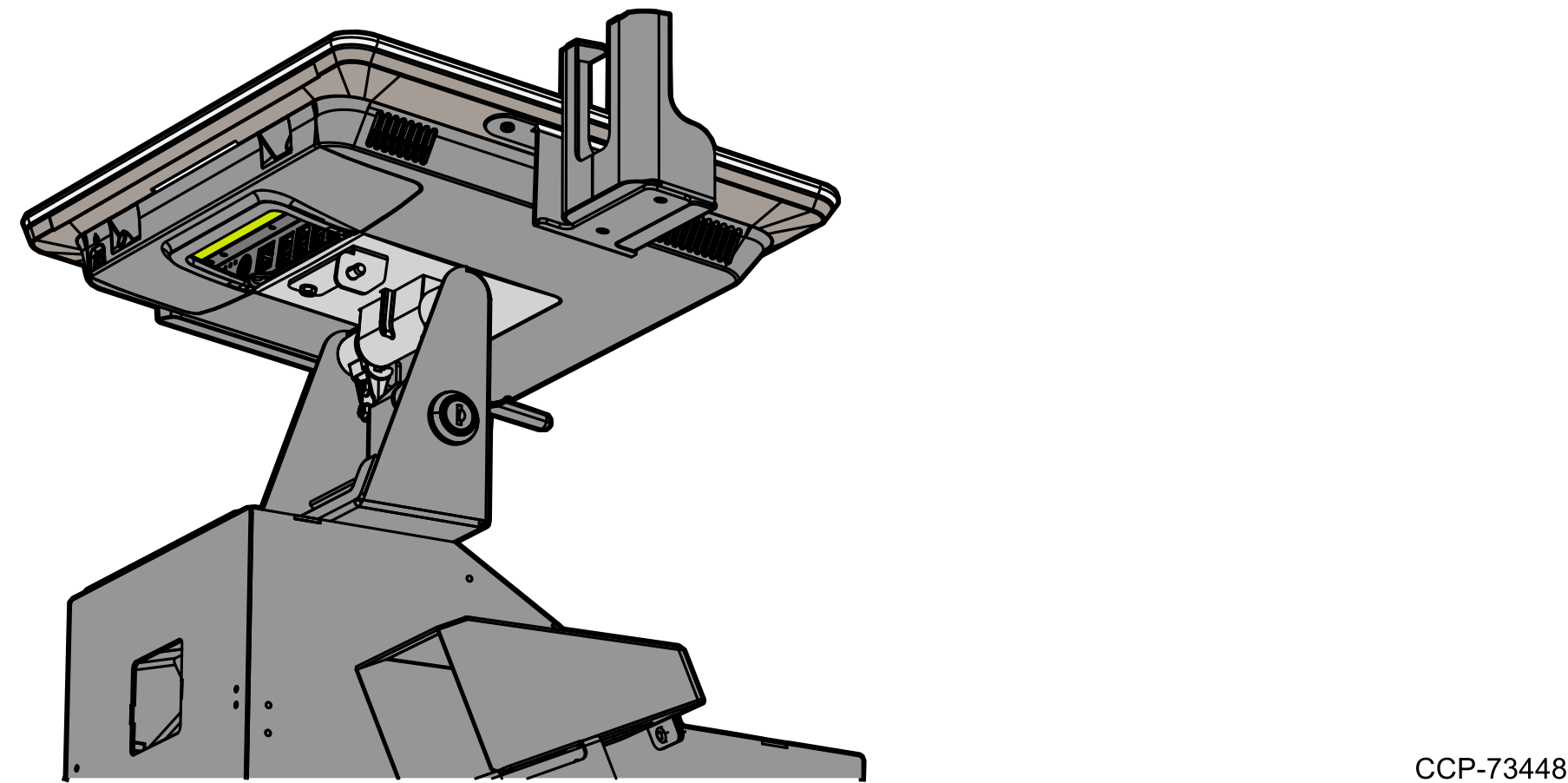
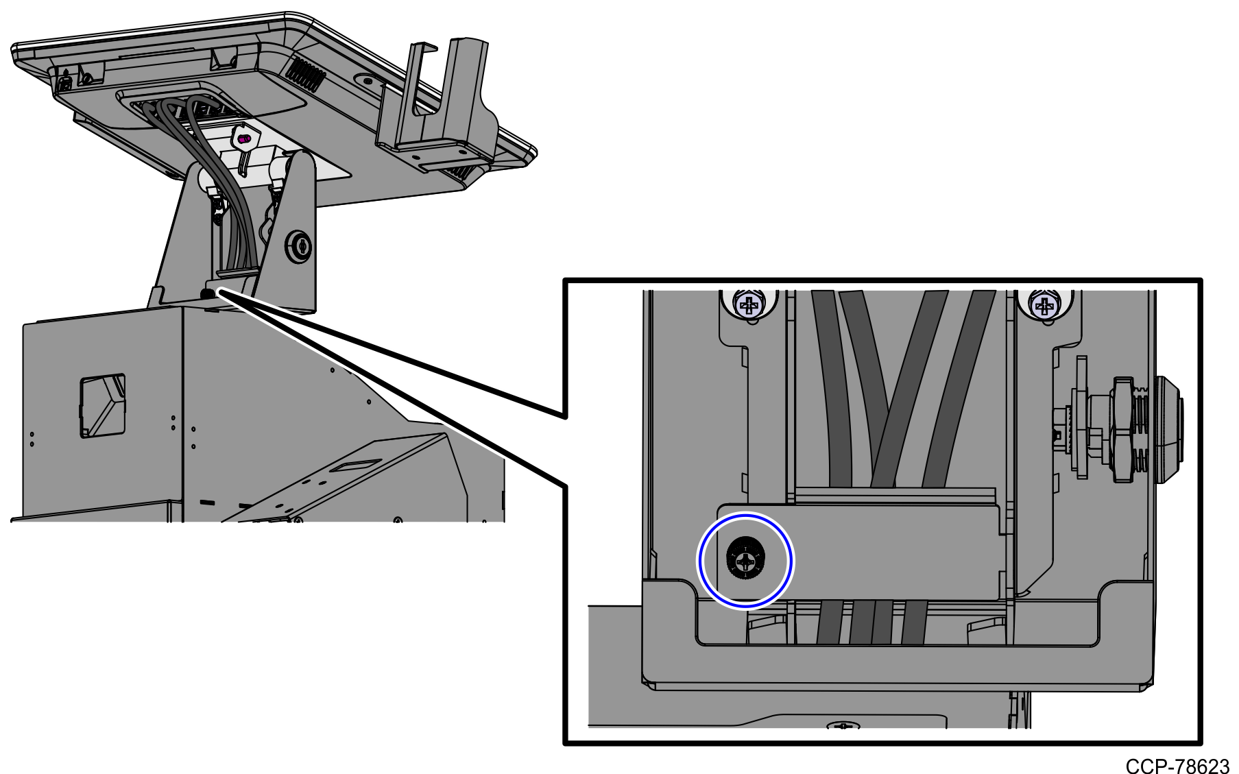
- Detach the cable guide by removing one (1) screw, as shown in the image below.
- Connect the USB-to-Serial adapter cable to the USB Port B of the NCR Terminal Display.Warning
Ensure that the system is turned off before disconnecting or connecting cables to avoid damaging the internal chip of the NCR Terminal Display and making the adapter unusable.
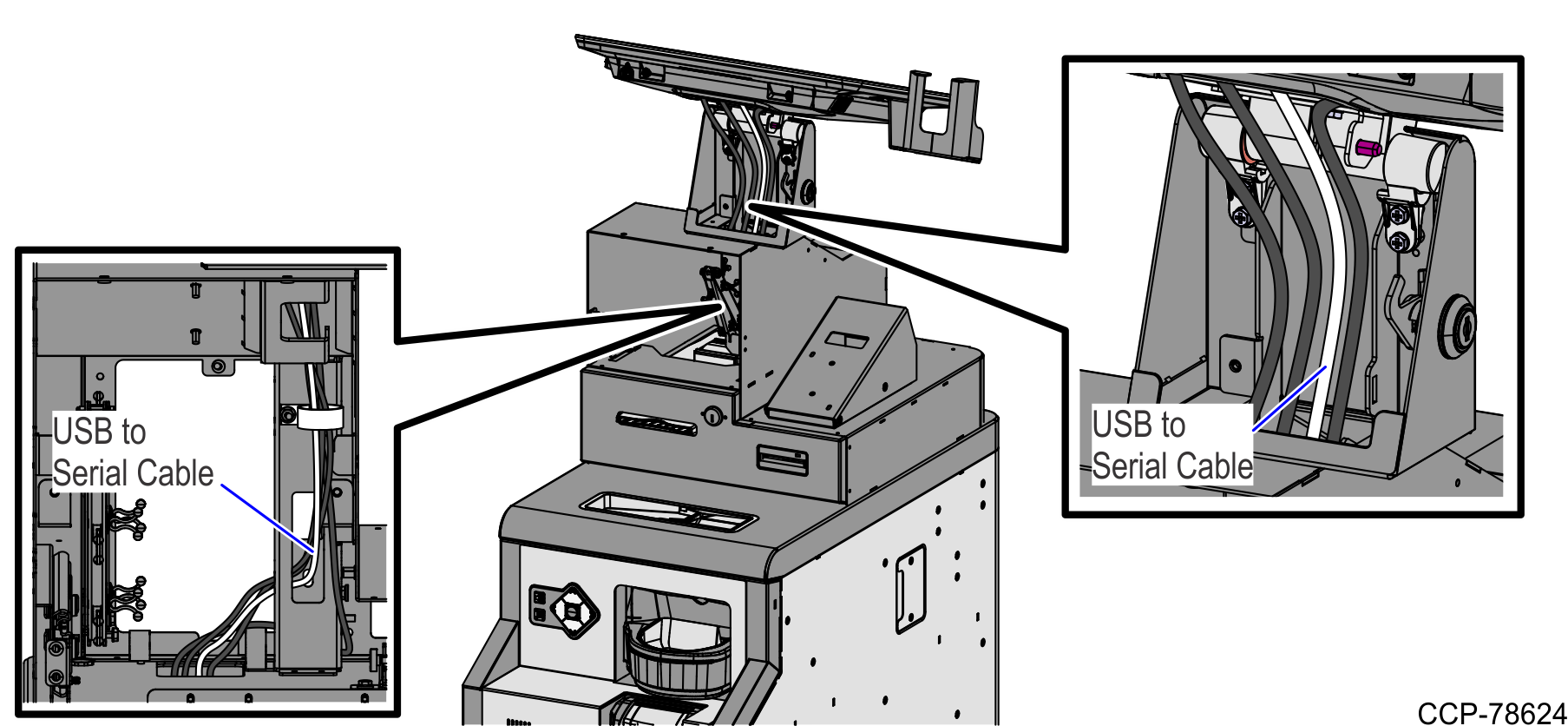
- Route the USB-to-Serial adapter cable along with the other cables from the Upper Enclosure going down to the Lower Cabinet.
- Attach the cable guide using one (1) screw.
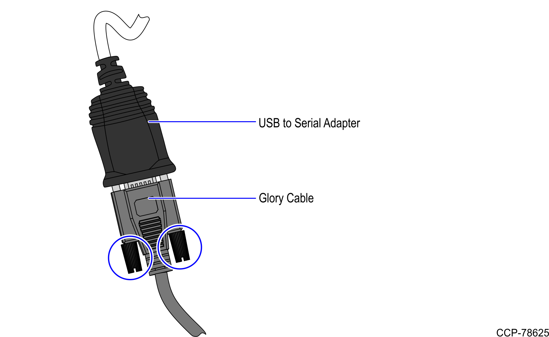
- Connect the currency device cable to the USB-to-Serial adapter cable and then secure the connection by tightening the two (2) screws.
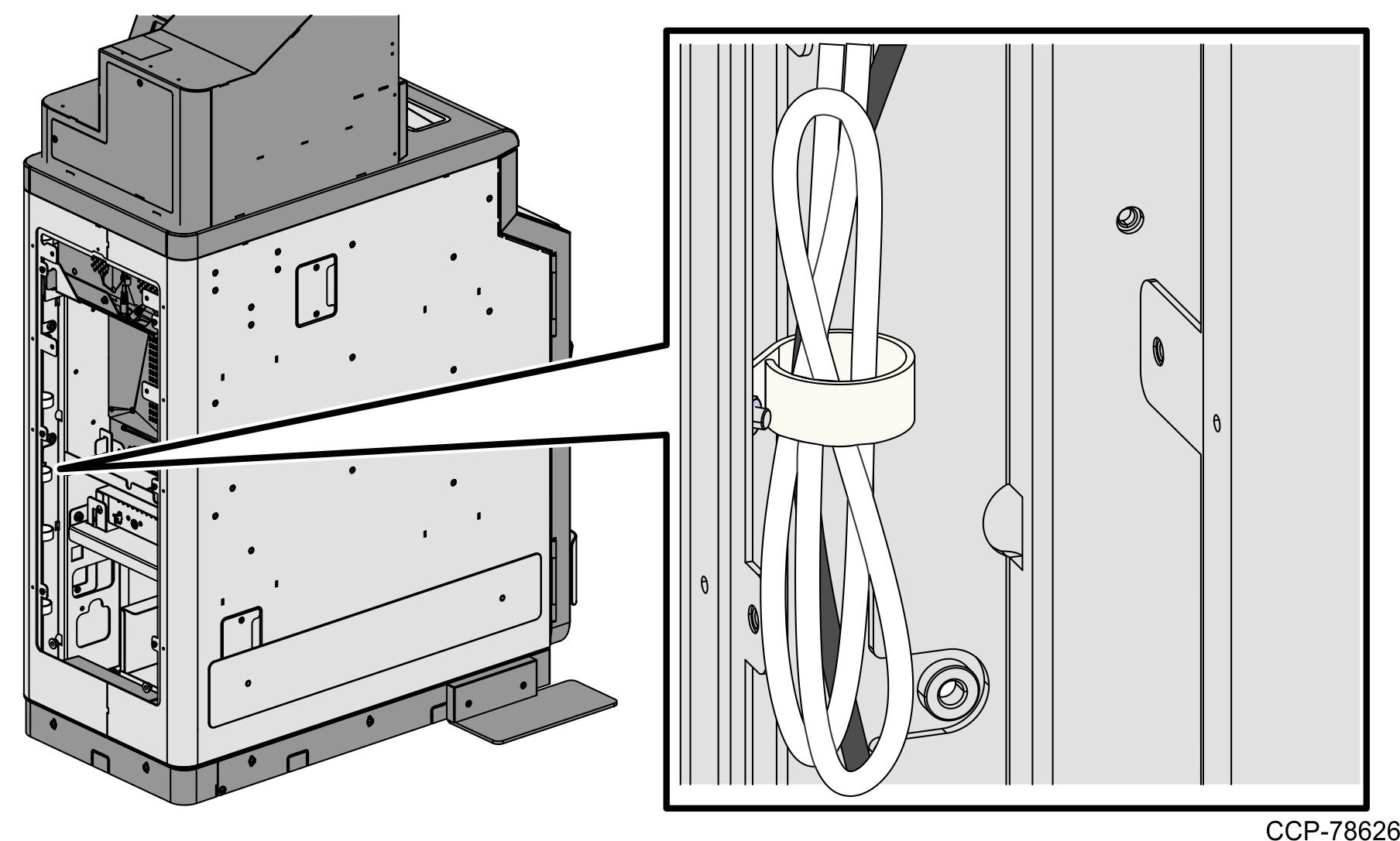
- Route the excess cable length on the rear left side of the lower cabinet by doing the following:
- Create a large loop.
- Insert the excess cable through the P-loop, as shown in the image below.
Connect the USB-to-Serial cable adapter to the Terminal Display (USB Port B ).
- Do the following:
- Attach the upper back panel back to the Tower Frame using two (2) screws.
- Attach the lower back panel to the lower cabinet using six (6) screws.
- Attach the upper back panel back to the Tower Frame using two (2) screws.
- Lower the NCR Terminal Display and then lock the Tower frame using a key.