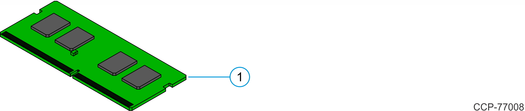
7772-K134/K136 Memory Module
This kit provides a memory module for NCR CX7 All-in-One POS (7772) or NCR CX8 POS (7736).
- 7772-K134 – 8GB Memory Module
- 7772-K136 – 16GB Memory Module
Kit Contents
| Item | Part Number | Description |
|---|---|---|
| 7772-K134 8GB Memory Module | ||
| 1 | 006-8626889 | Memory Module – 8GB, DDR4 2400MHz, SO-DIMM, 1.2V |
| 7772-K136 16GB Memory Module | ||
| 1 | 006-8626890 | Memory Module – 16GB, DDR4 2400MHz, SO-DIMM, 1.2V |
Installation Procedure
Warning
Disconnect the AC power cord from the AC outlet and wait 30 seconds before servicing the terminal.
NCR CX7 All-in-One POS (7772)
- Lay the Display face down on a flat surface.Note
Always use a soft material (cloth, foam) to protect the display screen when placing the terminal face down.
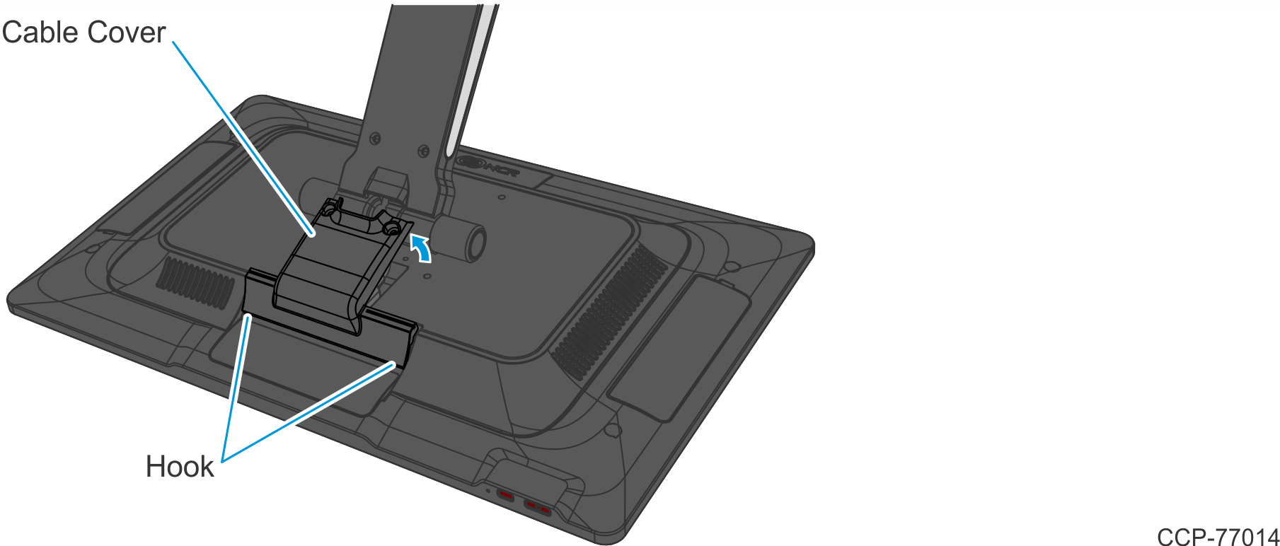
- Remove the Cable Cover.
- Remove the two (2) screws that secure the Cable Cover to the Back Cover.
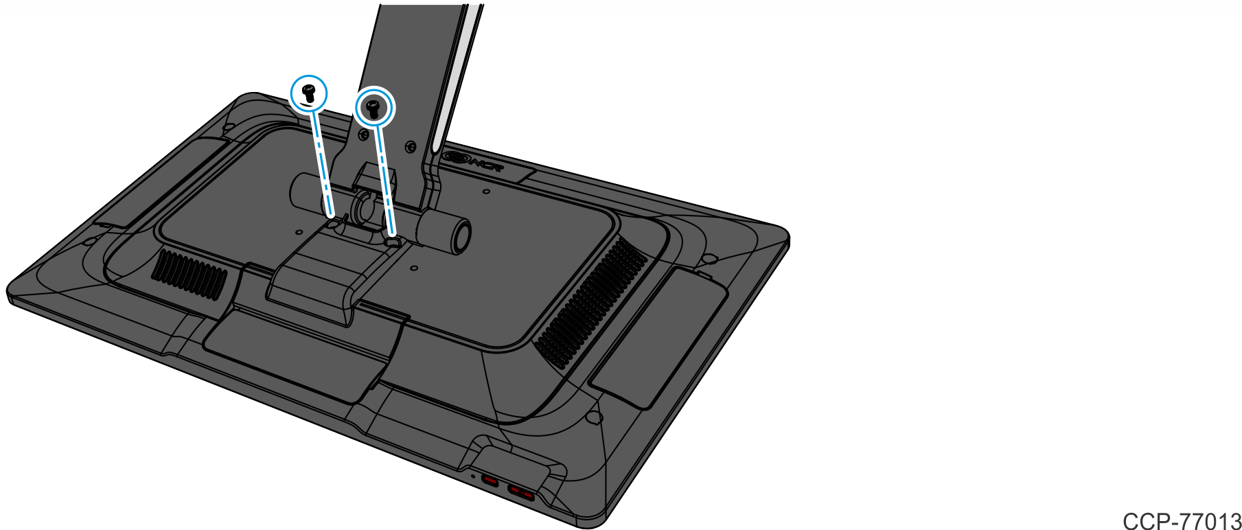
- Rotate and unhook the Cable Cover from the Back Cover.
- Remove the two (2) screws that secure the Cable Cover to the Back Cover.
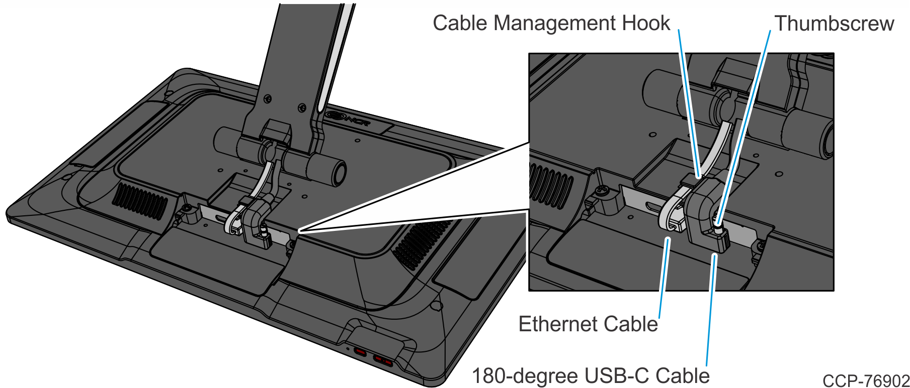
- Disconnect the Cables.
- Loosen the thumbscrew of the 180-degree USB-C Cable then disconnect the Cable.
- Remove the Ethernet Cable from the Cable Management Hook then disconnect the Cable.
- Loosen the two (2) captive screws that secure the Back Cover to the Display.
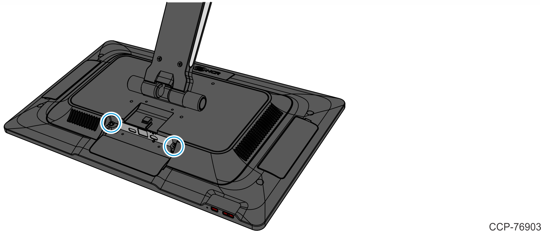
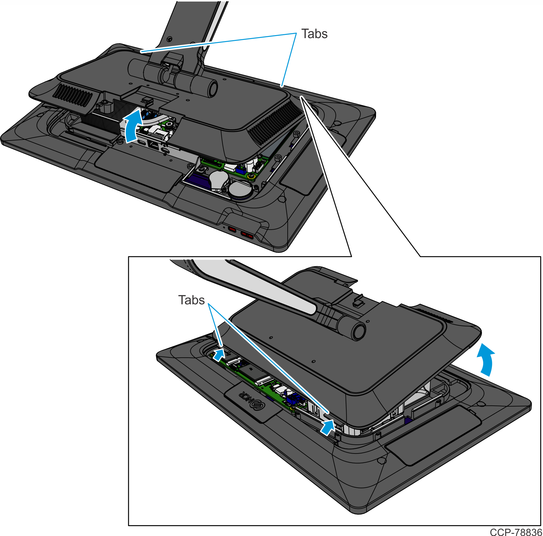
- Rotate the Back Cover away from the Display and unhook the Back Cover Tabs.
- Install the Memory Module in the Socket at an angle as shown.Note
Memory configurations containing a single memory module should be installed in the lower socket (Socket 1). Memory can be expanded by installing a second module in the upper socket (Socket 2).
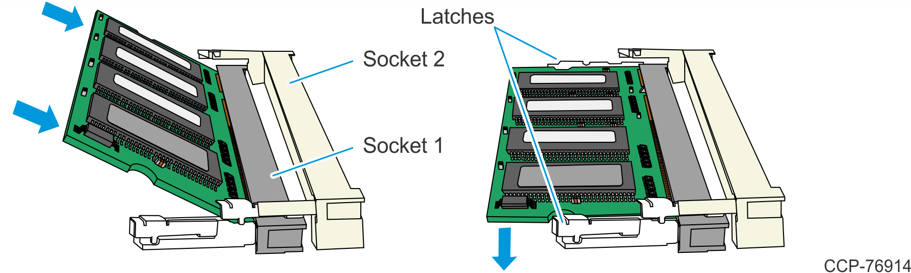
- Press the Memory Module down until it latches in position. Ensure the latches are completely engaged.
- Reinstall the Display Back Cover.
- Reconnect the 180-degree USB-C Cable and Ethernet Cable.
- Reinstall the Cable Cover.
NCR CX8 POS (7736)
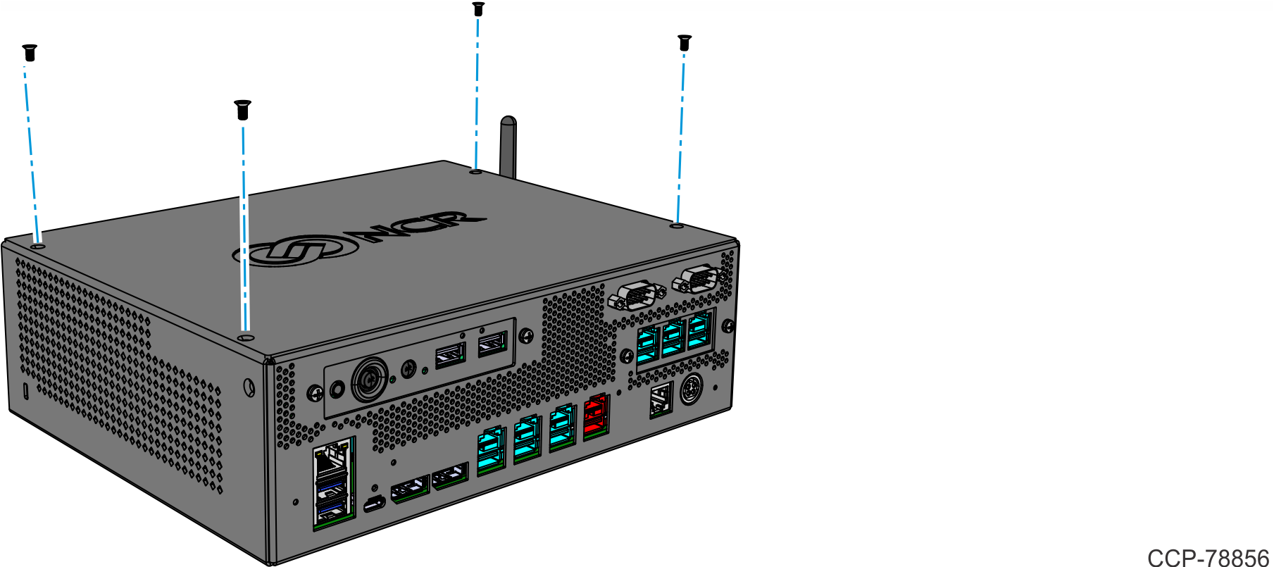
- Remove the Top Cover. There are two types of Top Covers:
- Top Cover without Duct — Remove the four (4) screws securing the Top Cover to the chassis.
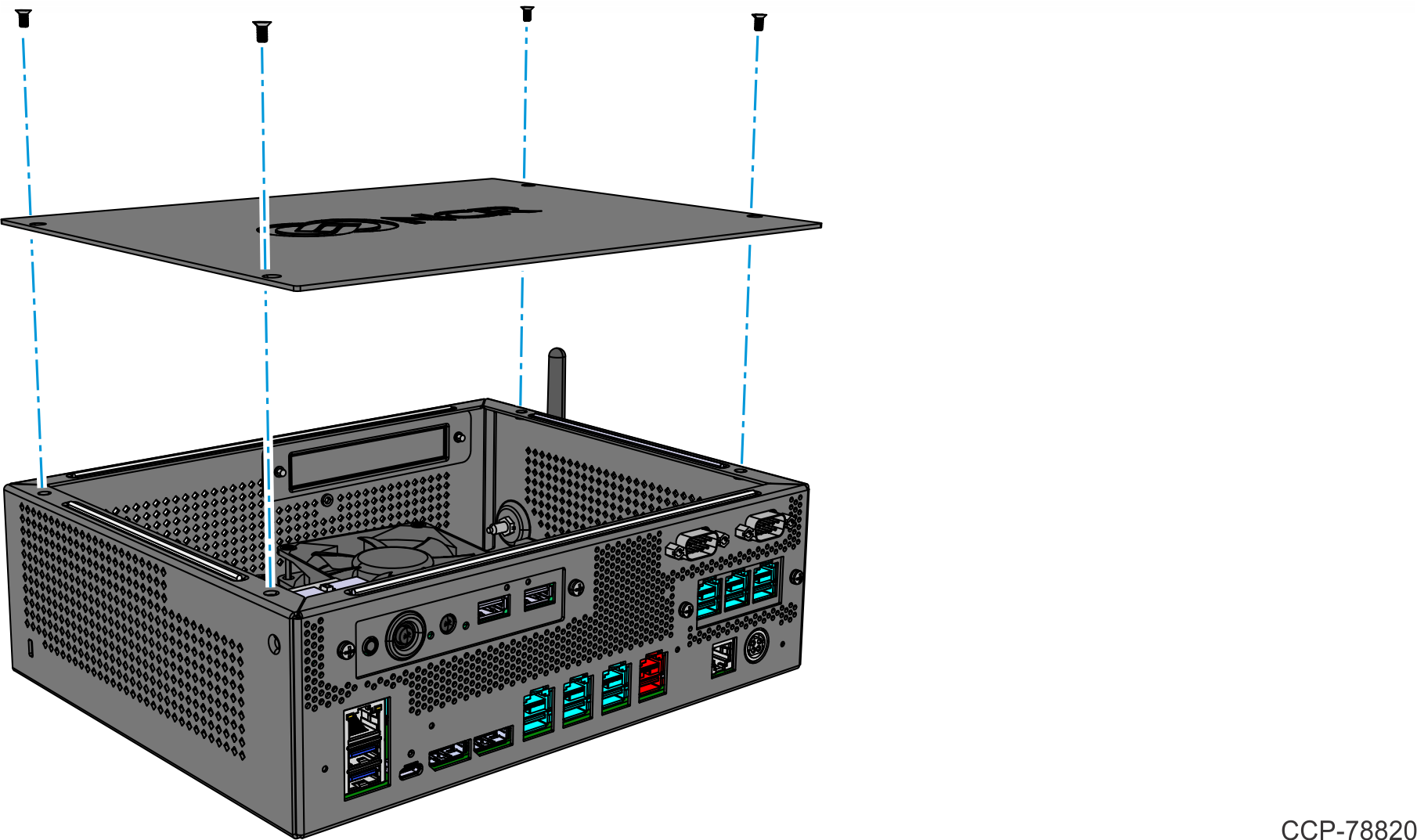
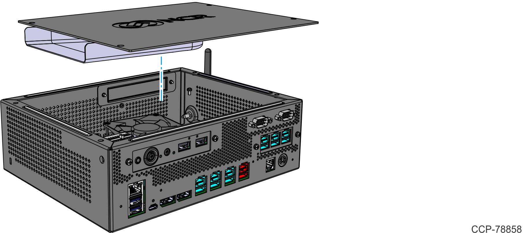
- Top Cover with Duct
- Remove the four (4) screws securing the Top Cover to the chassis.
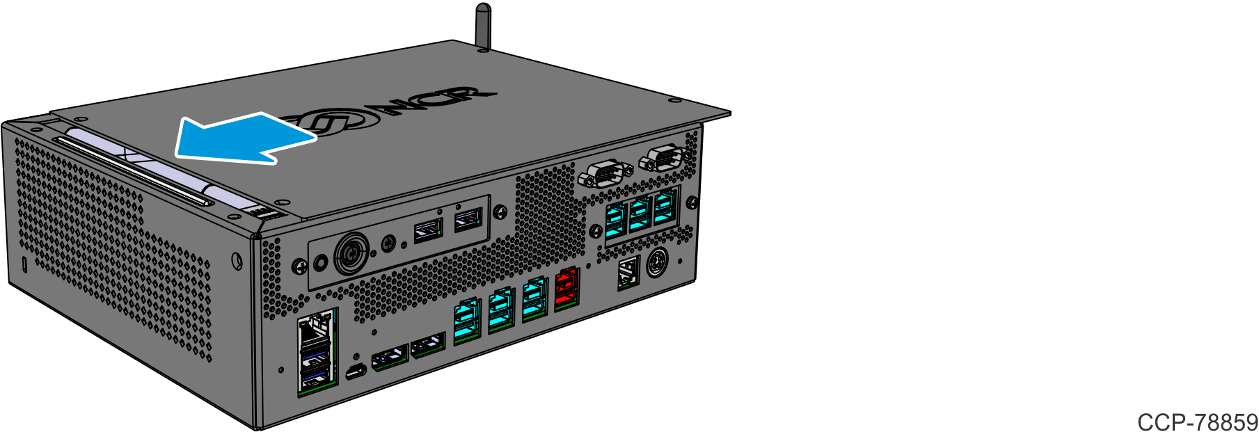
Slide the Top Cover in the direction shown.

- Top Cover without Duct — Remove the four (4) screws securing the Top Cover to the chassis.
- Install the Memory Module in the Socket at an angle as shown.Note
Memory configurations containing a single memory module should be installed in the lower socket (Socket 1). Memory can be expanded by installing a second module in the upper socket (Socket 2).
- Press the Memory Module down until it latches in position. Ensure the latches are completely engaged.
- Reinstall the Top Cover.
- Top Cover without Duct – Install the Top Cover on the chassis using four (4) screws.
- Top Cover with Duct
- Set the Top Cover on the chassis.
- Slide the Top Cover in the direction shown to align the screw holes of the Cover with the screw holes of the chassis.
- Secure the Top Cover with four (4) screws.
- Top Cover without Duct – Install the Top Cover on the chassis using four (4) screws.
