7772-K475 High Mount XL10 Customer Display Bracket, CX
This kit provides a Bracket to Mount the XL10 Customer Display on the CX head.
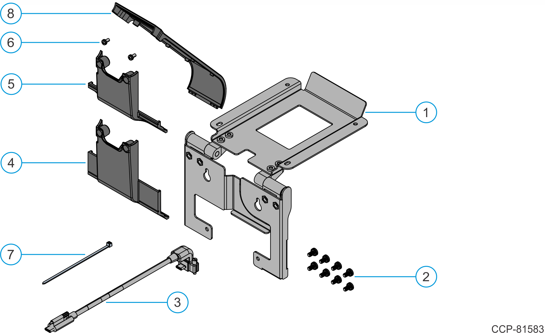
Kit Contents
| Item | Part Number | Description |
|---|---|---|
| 1 | 497-0531229 | Bracket Assembly, XL10 Display, High Mount, CX |
| 2 | 006-8627600 | Screw, M4x8, Phillips, Cross Recessed Pan Head Machine Screw with External Tooth Lock Washer, Black, Zinc |
| 3 | 497-0529413 | Cable, USBC, 10” Customer Display, 506mm |
| 4 | 497-0531570 | Cable Cover, Cast, Black |
| 5 | 497-0531574 | 4:3 Cable Cover, Cast |
| 6 | 497-0480152 | Screw, M3x6mm, Machine, Phillips, Pan Head |
| 7 | 006-8616073 | Cable Tie, 2.5mm width, 100mm length |
| 8 | 497-0523787 | Neck, Outer, Black (Back Neck Cover) |
Installation Procedure
Warning
Disconnect the AC power cord from the AC outlet and wait 30 seconds before servicing the terminal.
- Lay the Display face down on a flat surface.
Always use a soft material (cloth, foam) to protect the display screen when placing the terminal face down.
- Remove the Cable Cover.
- Remove the two (2) screws that secure the Cable Cover to the Back Cover.
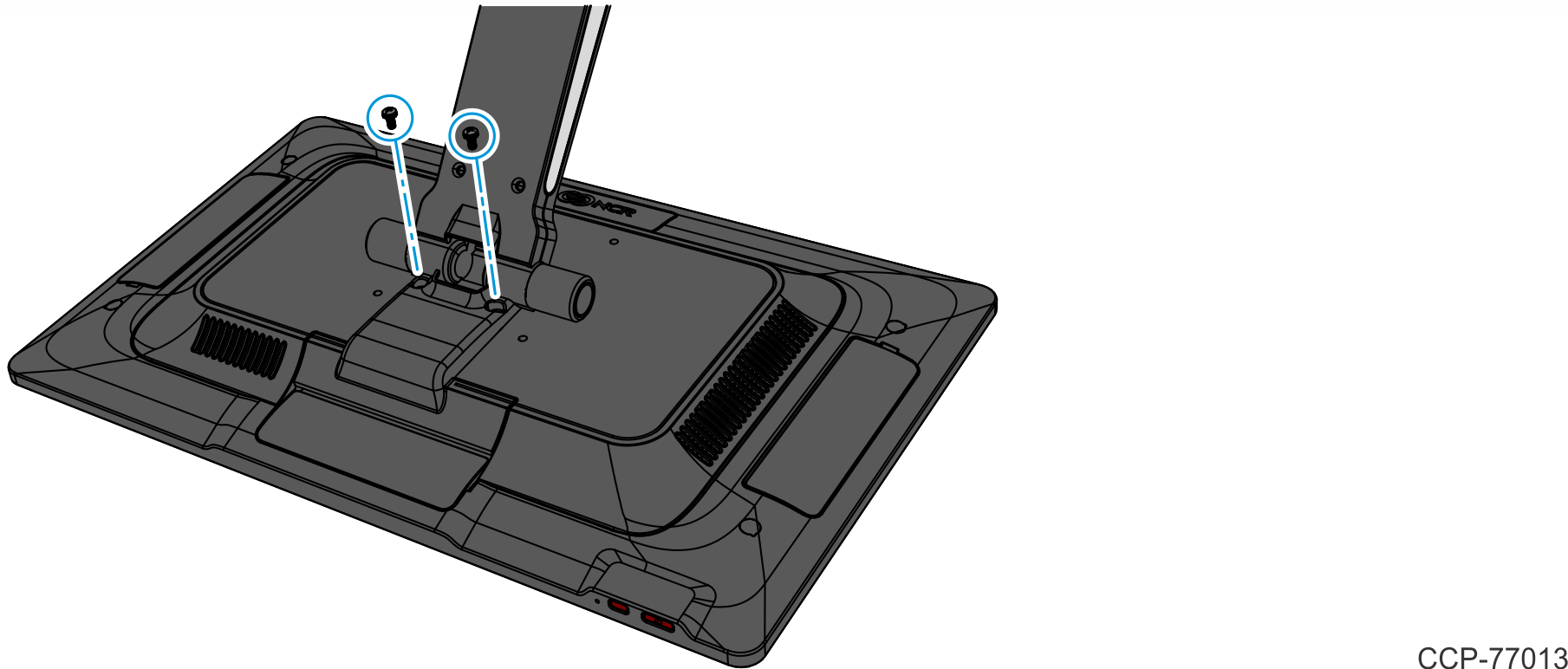
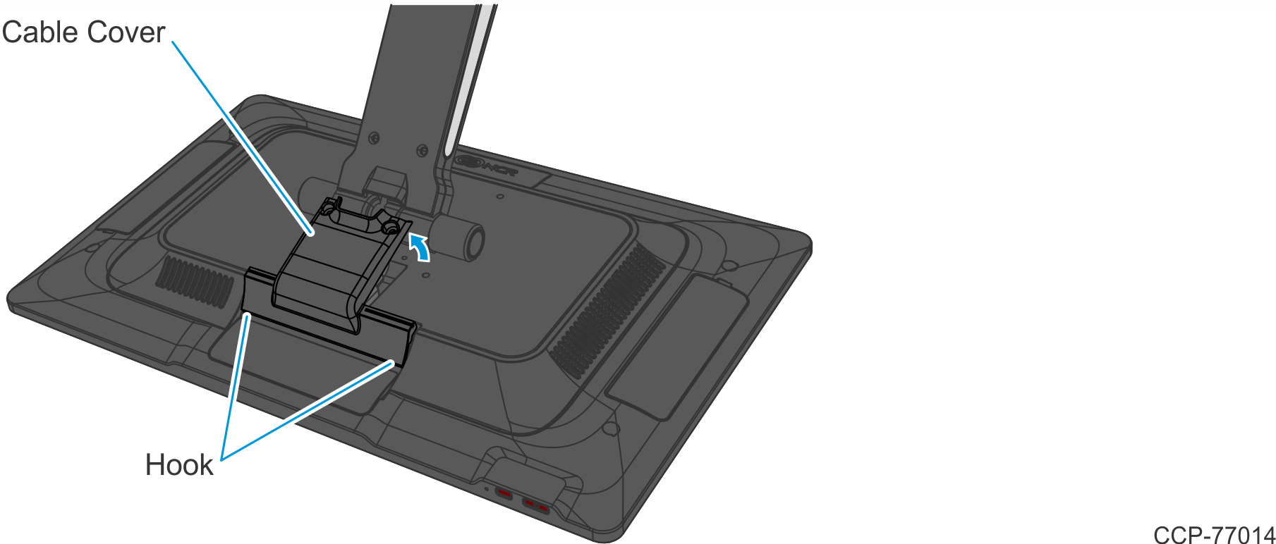
- Rotate and unhook the Cable Cover from the Back Cover.
- Remove the two (2) screws that secure the Cable Cover to the Back Cover.
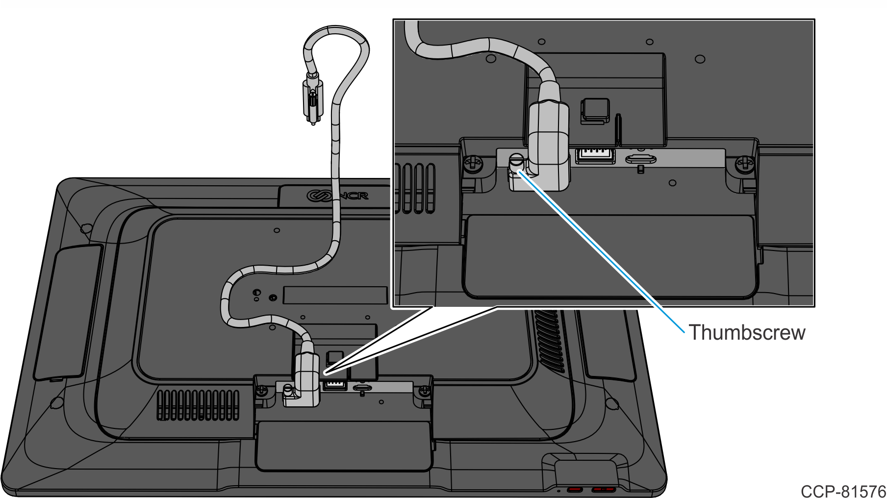
- Connect the USB-C Cable to the CX7 Display and tighten the thumbscrew.
For clarity, the Neck is not shown in the illustration below and in the succeeding illustrations.
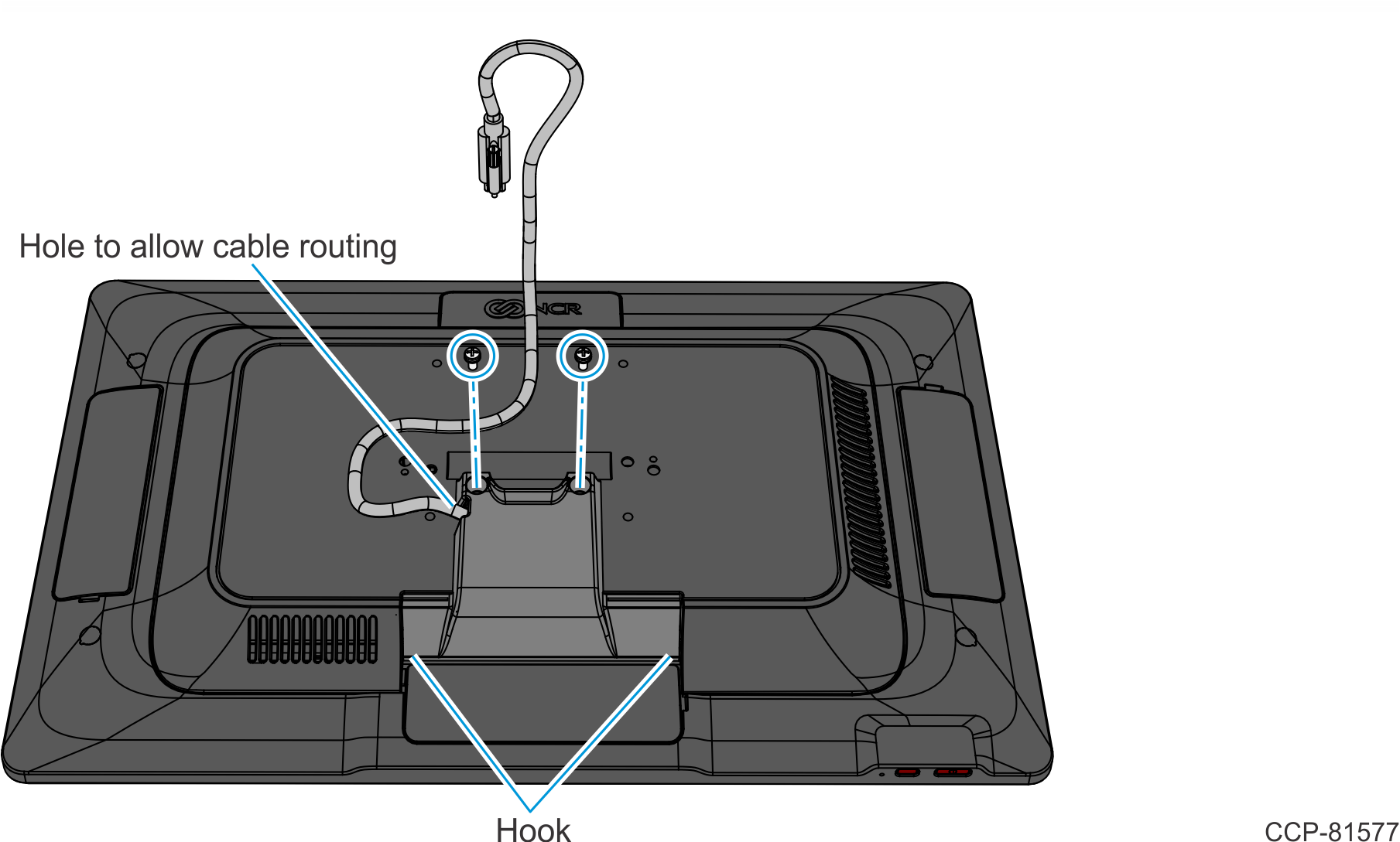
- Install the new Cable Cover. The new Cable Cover has a hole on the side to allow cable routing.
- Hook the bottom of the Cable Cover to the Back Cover, then rotate the Cable Cover into place.
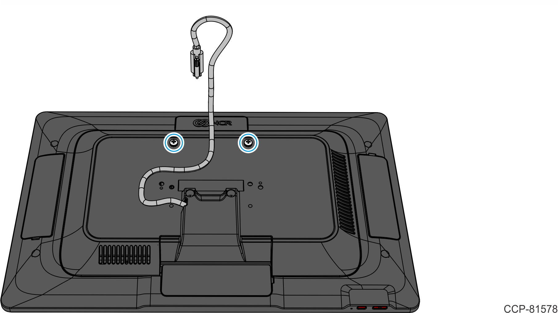
- Secure the Cable Cover with two (2) screws.
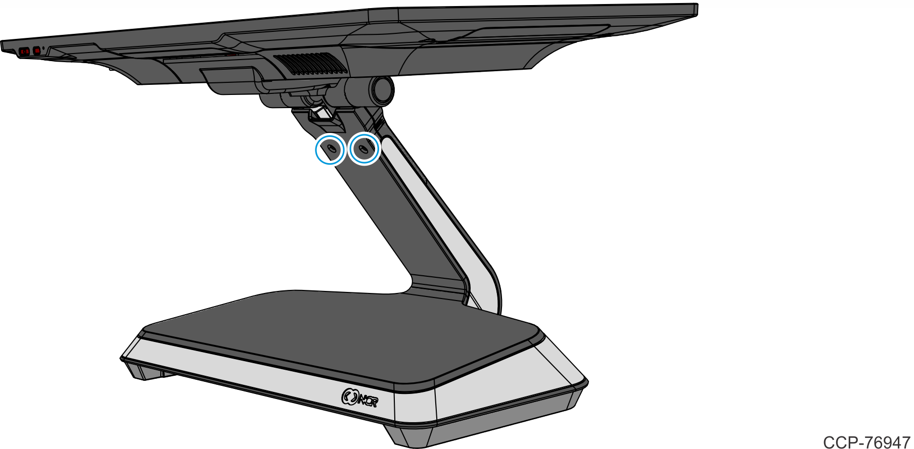
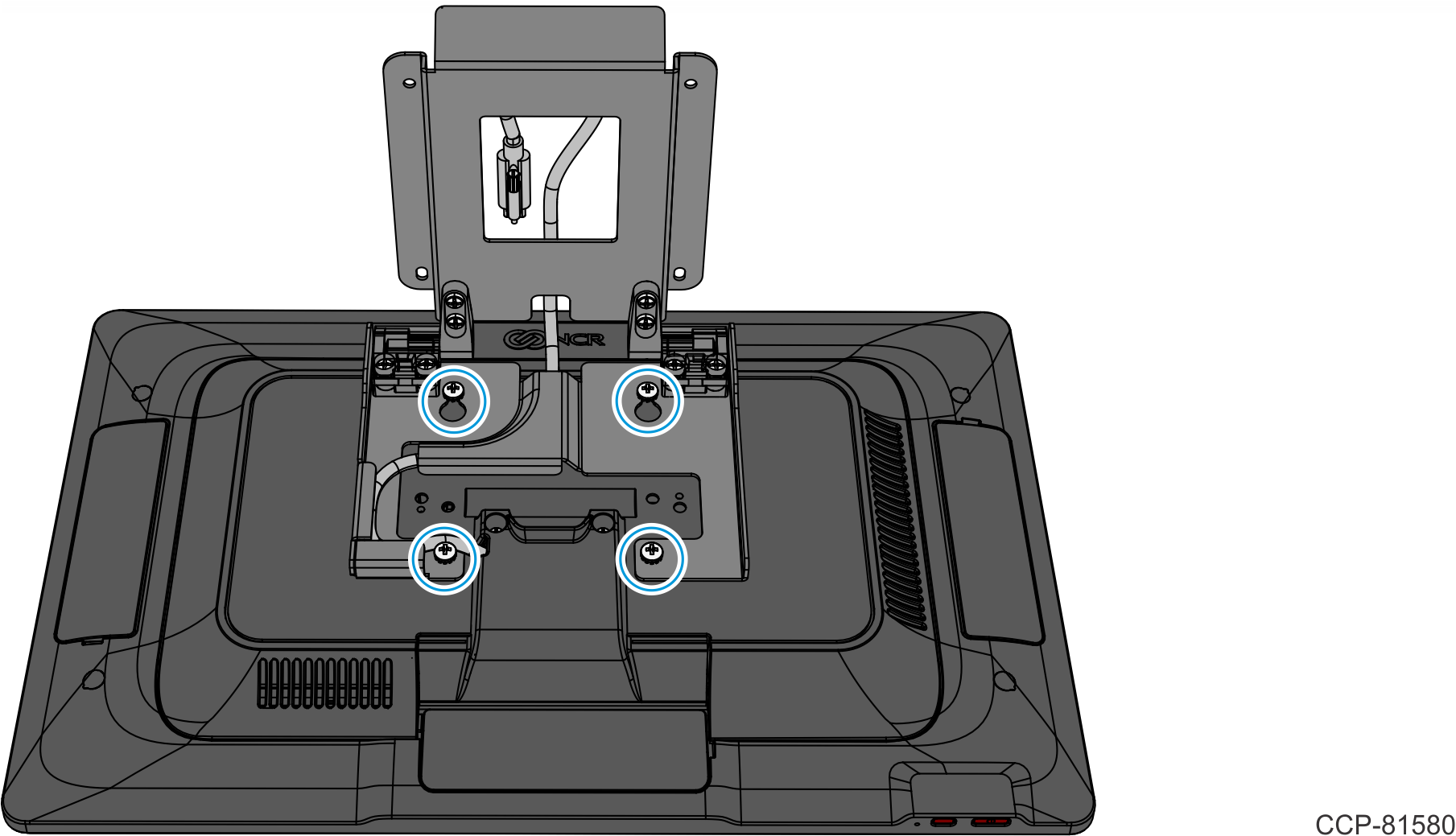
- Partially install two (2) screws on the back of the CX7 Display in the location shown.
- Hook the Bracket on the partially installed screws. Ensure the Cable is routed as shown.
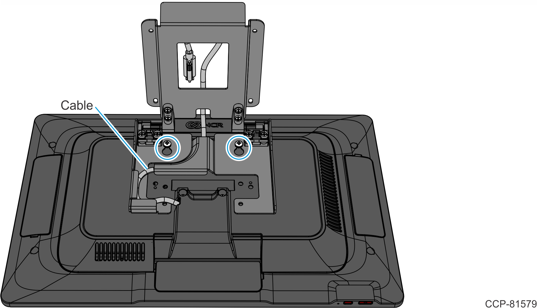
- Tighten the two (2) partially installed screws and install two (2) screws on the bottom of the Bracket.
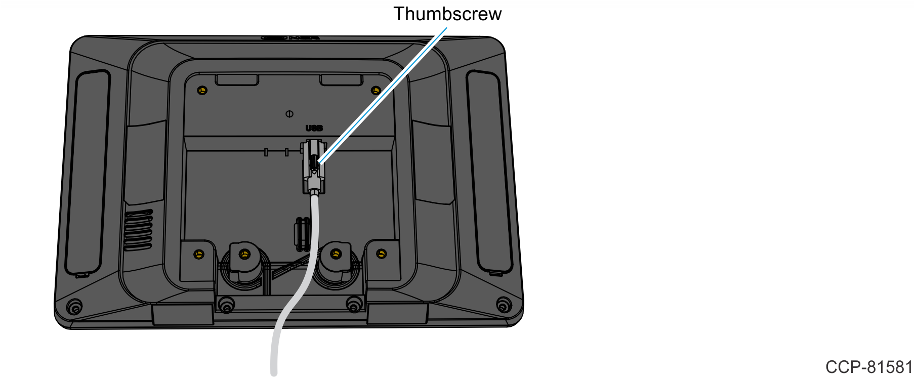
- Connect the other end of the Cable to the back of the XL10 Customer Display and tighten the thumbscrew.
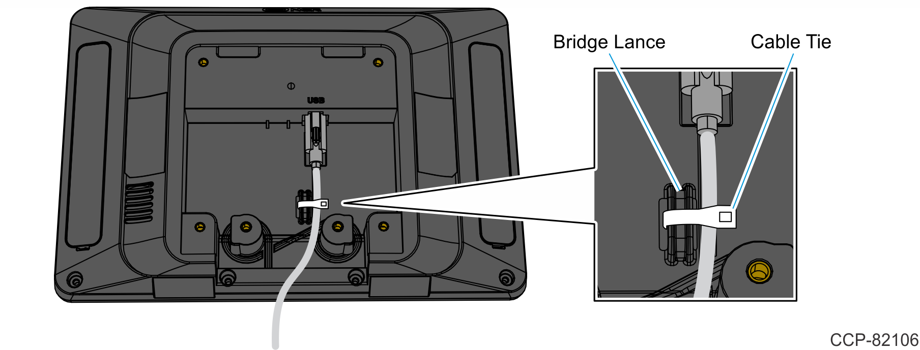
- Secure the Cable on the side of the bridge lance using a cable tie as shown.
- Install the XL10 Customer Display on the Bracket (4 screws). Ensure the Cable is routed through the gap in the Bracket as shown.
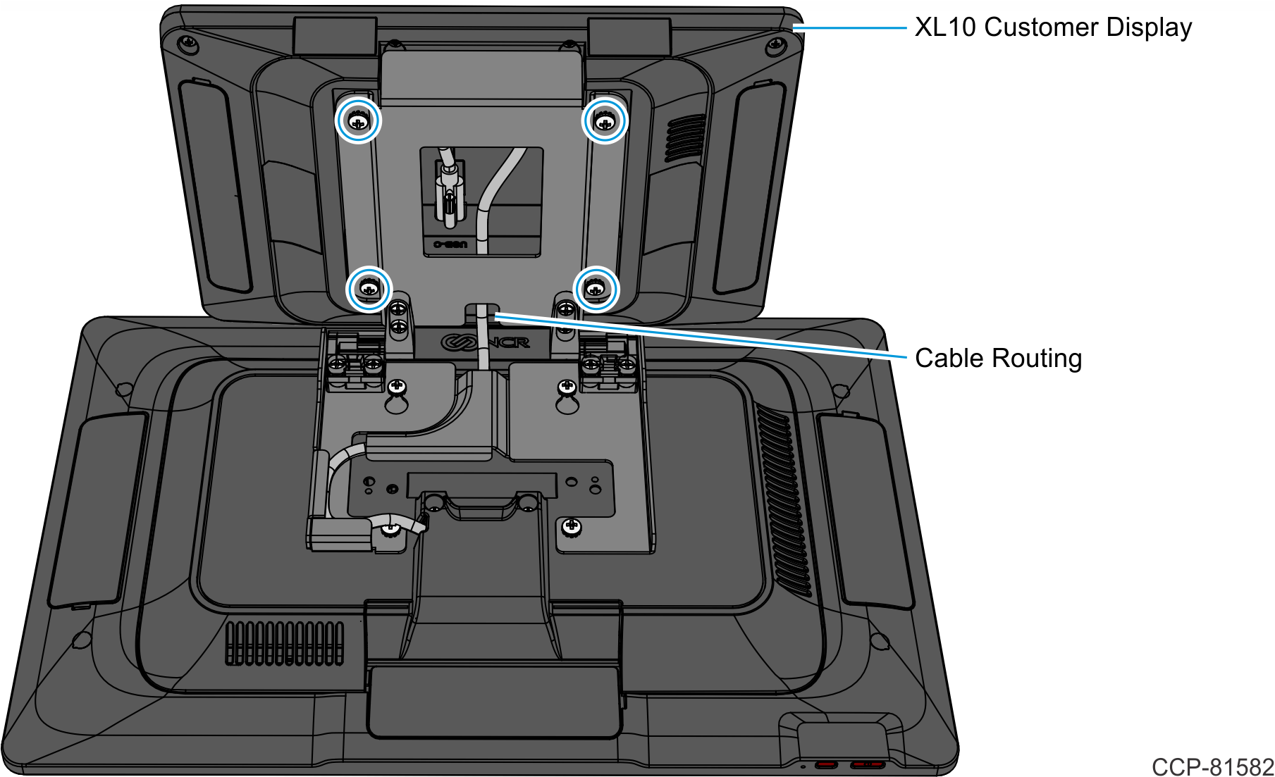
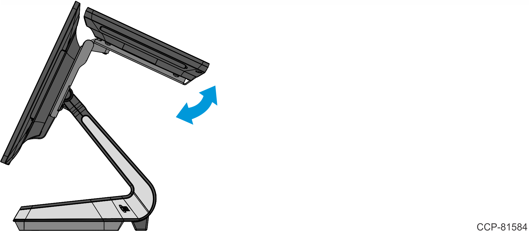
- Pivot the XL10 Customer Display into position.
Installing the Back Neck Cover
The kit includes a Back Neck Cover (497-0523787). The Back Neck Cover is required when converting from XL10 Base Display (F455/K455) to XL10 High Mount (K475).
Note
For clarity, the XL10 mounted on the CX head is not shown in the succeeding illustrations.
- Snap the Back Neck Cover onto the neck. The Cover has a simple snap fit connection at the top.

- Install the Base Rear Foot (2 screws). Ensure the Neck Cover is captured under the Base Rear Foot.Note
The Base Rear Foot serves to manage the cables and hold the bottom of the Neck Cover in place.

- Attach the Front Neck Cover to the Neck.
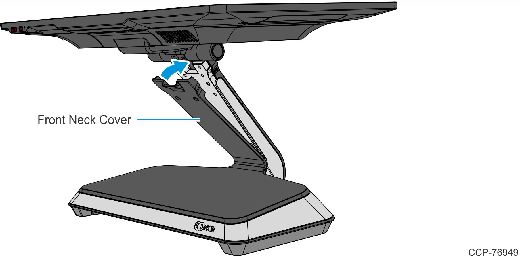
- Secure the Front Neck Cover to the Neck with two (2) screws. Use the appropriate screws:
- flat head screws for Base without Integrated Power Supply
- thumbscrews for Base with Integrated Power Supply