7879-K151 Integrated Customer Scanner
The Integrated Customer Scanner (ICS) is located on the back of the Tower Cabinet (Cosmetic Cover) and can be used by the customer to scan items such as coupons. This includes printed coupons and coupons displayed on an electronic device such as a Smart Phone.
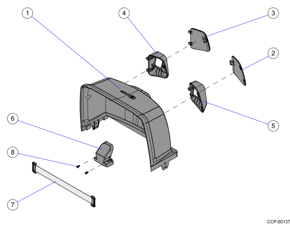
Components
|
Item |
Part Number |
Description |
|---|---|---|
|
1 |
497–0504975 |
Cosmetic Tower |
|
2 |
497–0501285 |
Cosmetic Cover, Blank, Right |
|
3 |
497–0501286 |
Cosmetic Cover, Blank, Left |
|
4 |
497–0501287 |
Customer Camera Shroud, Right |
|
5 |
497–0501288 |
Customer Camera Shroud, Left |
|
6 |
497–0501858 |
Rear Camera Assembly |
|
7 |
497–0502200 |
Harness, Latching, Shielded, 41 Pins, 0.5mm, 26cm Length |
|
8 |
006–8624571 |
Screw, WN1411 K30 X 8 Phillips OVL HD PT SCR Steel Zinc |
Tool Required
•#1 Phillips screwdriver
Installation Procedure
Caution: Before performing the procedures indicated below, remove power from the NCR 7879.
Remove the Top Plate
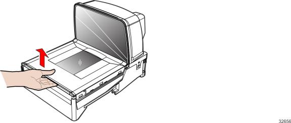
1.Hold the front edge of the Top Plate between your fingers.
2.Lift the Top Plate to remove it from the NCR 7879.
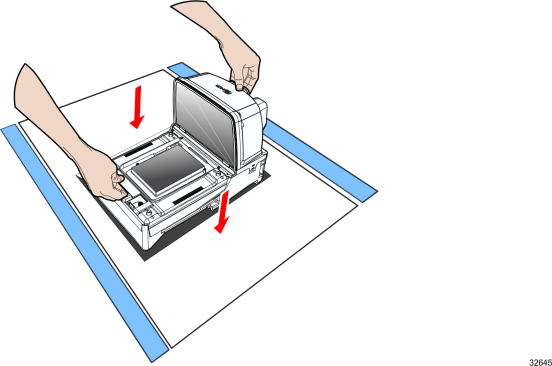
Remove the NCR 7879 from Checkstand
Note: This procedure is for NCR 7879 scanners that are installed in a Checkstand. If a Checkstand is not used, skip to "Remove the Old Tower Cabinet" section.
1.Holding the handles on the back of the Tower Cabinet and the front of the Debris Guard, slowly lift the NCR 7879 out of the Checkstand.
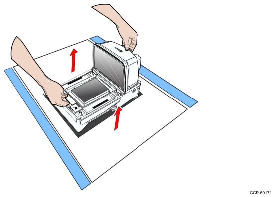
2.Place the NCR 7879 on a flat surface.
Note: If cables prevent the unit from sitting on a flat surface, disconnect the cables.
3.Proceed to the "Remove the Old Tower Cabinet" section..
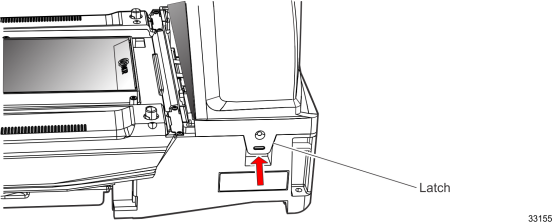
Remove the Old Tower Cabinet
The Tower Cabinet is secured with two Latches, one on each side.
1.The Latches may be secured with a Screw; however, Screws are not installed during manufacturing. If Screws are being used, remove them so that the Latches are permitted to move out and release from the Horizontal Base Assembly.
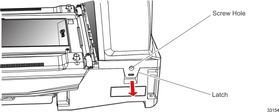
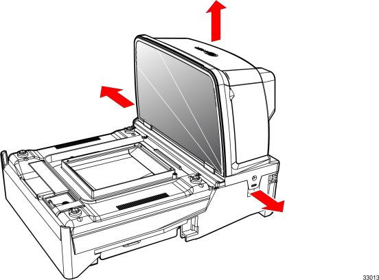
2.Move the two Latches toward the outside of the scanner to release them.
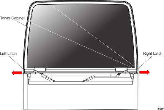
3.While holding the Latches out, lift the old Tower Cabinet up and off the NCR 7879.
Note: The old Tower Cabinet may be discarded.
Install the Integrated Customer Scanner
Caution: Do not remove the ESD Protection Pads (gaskets) from the K151 Tower Cabinet.
The Tower Cabinet that comes with the ICS kit has two holes on the back, and the ICS can be mounted on either side of the Tower Cabinet. The side without the ICS is fitted with a Blank Cosmetic Cover.
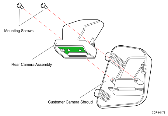
1.Attach the Rear Camera Assembly to a Customer Camera Shroud and secure using two Mounting Screws.
Note: To avoid damage to the ICS parts, be careful not to overtighten the screws.
2.Mount the Customer Camera Shroud with Rear Camera Assembly through the corresponding hole and secure with three latches.
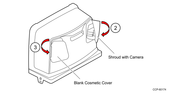
3.Mount a Blank Cosmetic Cover through the other hole of the K151 Tower Cabinet and secure with three latches.
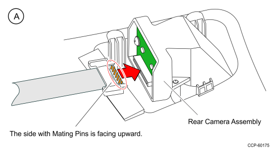
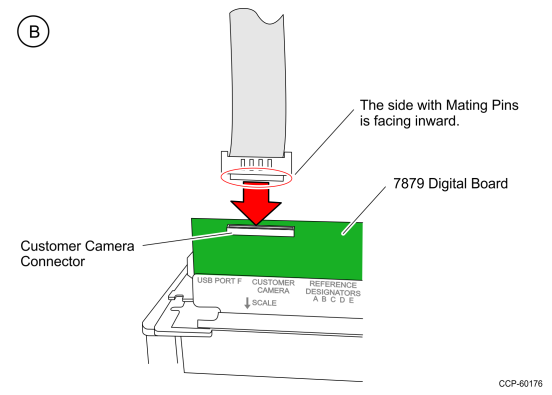
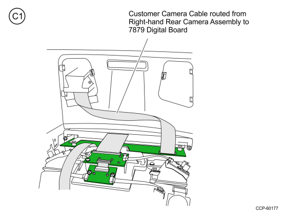
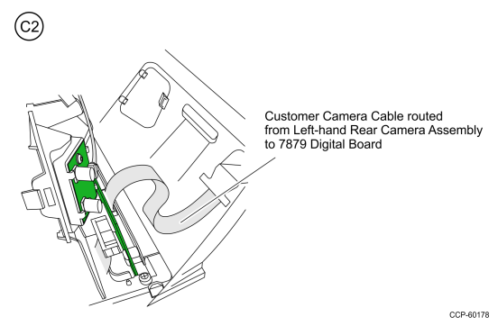
4.Connect one end of the Customer Camera Cable to the Rear Camera Assembly (A) and the other end to the NCR 7879 Digital Board (B) found at the back of the unit. Follow the proper cable routing for Right–hand (C1) and Left–hand (C2) setup.
Note: Ensure that the Customer Camera Cable is not creased.
Install the K151 Tower Cabinet
1.Carefully position the K151 Tower Cabinet down over the Tower Assembly. Make sure it is properly positioned on the NCR 7879 so that the Side Latches can engage.
2.Slide the K151 Tower Cabinet down to engage the latches.
3.Slightly push the Latches toward the center of the scanner to make sure they are engaged.
4.If Screws were used in the Latches, install and tighten the Screws.
Install the NCR 7879 in Checkstand
Note: This procedure is for NCR 7879 scanners that are installed in a checkstand. If a checkstand is not used, skip to "Install the Top Plate" section.
1.If cables were removed, reconnect them to the NCR 7879.
2.Holding the handles on the back of the Tower Cabinet and the front of the Debris Guard, slowly lower the NCR 7879 into the checkstand cutout. It should sit on the designated supports.
3.Proceed to the "Install the Top Plate" section.
Install the Top Plate
1.Position the Top Plate over the front of the NCR 7879.
2.Lower the Top Plate until it is supported by the Supporting Studs. The Top Plate should be properly aligned with the NCR 7879 and should not move in a horizontal direction.
Note: After installing the Top Plate, restore power to the NCR 7879.
Programming Instructions
Note: The customer–side and cashier–side images are programmed independently; however, the Integrated Customer Scanner (ICS) will NOT independently enumerate with OPOS.
The ICS comes with three LEDs, which have no independent behavior from each other (they work together). This camera is defaulted to Autodetect mode but can be turned off (deactivated) with programming.
When the camera is detected by the 7879, the ICS LEDs turn blue, indicating that the camera is active but, by default, no ICS symbologies are enabled. When one or more ICS symbologies are enabled, the ICS LEDs turn from blue to green.
Also, when the camera is detected, the default beep frequency of the ICS is three positions higher in the frequency list from the default 7879 beep frequency.
Note: For proper functionality, the ICS requires the latest firmware 497–0506421 or higher.
Programming the NCR 7879 for ICS
To program the NCR 7879 for the ICS, perform these steps:
1.Power up the NCR 7879. The ICS is automatically detected by the NCR 7879, and the ICS LEDs turn blue.
2.Allow the pass–through of 1D and 2D data to the POS.
a.Enable any of the 1D or 2D tags. For the programming sequences, refer to the "Programming Worksheets" section.
b.Enable 1D and 2D pass–through function of the enabled barcode types by scanning the Save and Reset tag. For the programming tags, refer to the "Programming Tags" section.
c.Test the ICS to validate its functionality. Refer to the "Testing the Integrated Customer Scanner" section.
Testing the Integrated Customer Scanner
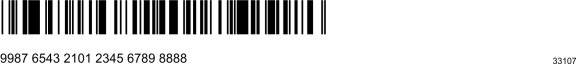
To confirm if the ICS is properly set up, apply a program sequence to enable one of the ICS symbologies (for example, PDF417) and scan a corresponding barcode at the ICS rear–facing window. If the barcode is successfully read, a beep should then be heard.

Sample PDF417 Barcode
Programming Worksheets
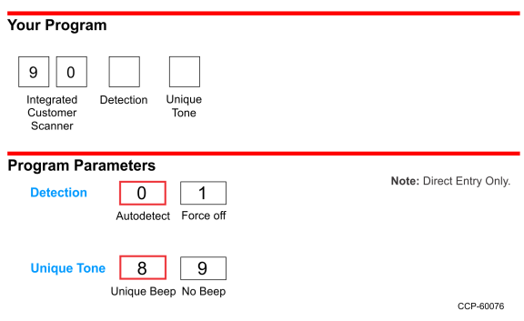
Detection
By default, the Autodetect mode in turned on. To disable, scan the Hex 1 tag.
Unique Tone
By default, the Unique Tone is enabled and thus, a unique beep is heard when items are scanned with the ICS. To disable, scan the Hex 9 tag.
Integrated Customer Scanner (ICS) Symbology Enable 1
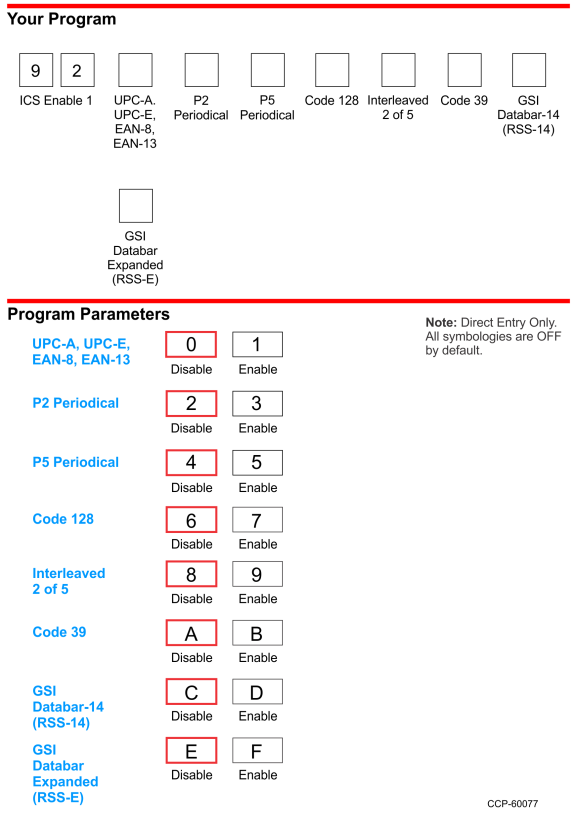
UPC-A, UPC-E, EAN-8, EAN-13
The UPC/EAN parameter controls reading of UPC/EAN bar codes by the ICS. Disable reading UPC/EAN bar codes by scanning the Hex 0 tag and enable reading by scanning the Hex 1 tag.
UPC-A and UPC-E are the most common bar code types in the US, while EAN-8 and EAN-13 are the most common types in Europe.
P2 Periodical
The P2 Periodical parameter controls reading of 2-digit periodical bar codes by the ICS. Disable reading 2-digit periodical bar codes by scanning the Hex 2 tag and eable reading by scanning the Hex 3 tag.
This type of bar code is commonly seen next to a UPC or EAN bar code on newspapers and magazines.
P5 Periodical
The P5 Periodical parameter controls reading of 5-digit periodical bar codes by the ICS. Disable reading 5-digit periodical bar codes by scanning the Hex 4 tag and eable reading by scanning the Hex 5 tag.
This type of bar code is commonly seen next to a UPC or EAN bar code on greeting cards and some magazines.
Code 128
The Code 128 parameter controls reading of Code 128 bar codes by the ICS. Disable reading Code 128 bar codes by scanning the Hex 6 tag and enable reading by scanning the Hex 7 tag.
Interleaved 2 of 5
The Interleaved 2 of 5 parameter controls reading Interleaved 2 of 5 bar codes by the ICS. Disable reading Interleaved 2 of 5 bar codes by scanning the Hex 8 tag and enable reading by scanning the Hex 9 tag.
Code 39
The Code 39 parameter controls reading of Code 39 bar codes by the ICS. Disable reading Code 39 bar codes by scanning the Hex A tag and enable reading by scanning the Hex B tag. If reading Code 39 bar codes is disabled, there are no other entries permitted for this parameter.
GSI Databar-14 (RSS-14)
GS1 DataBar-14 is a linear symbology that encodes 14 UCC/EAN digits. This structure provides four segments that can be scanned and decoded separately, then reconstructed. The total symbol contains 96 modules combined into 46 elements (bars and spaces).
This symbology is commonly seen on produce items.

GSI Databar Expanded (RSS-E)
GS1 DataBar-Expanded is a variable length linear symbology. It can encode 74 numeric or 41 alpha characters. GS1 DataBar-Expanded can be scanned and decoded in up to 22 segments and then reconstructed.
This symbology is commonly seen on coupons and some deli items.
Integrated Customer Scanner (ICS) Symbology Enable 2
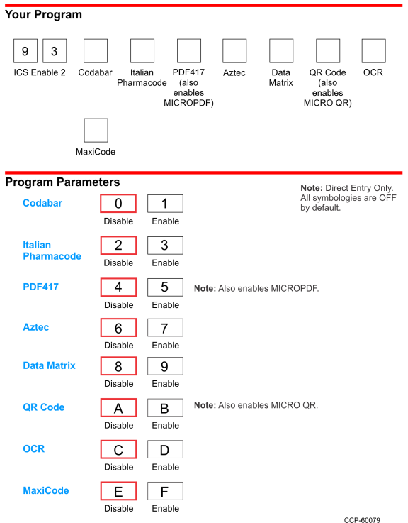
Codabar
The Codabar Decoding parameter controls reading Codabar bar codes by the ICS. Disable reading Codabar bar codes by scanning the Hex 0 tag, enable reading by scanning the Hex 1 tag.
Italian Pharmacode
The Italian Pharmacode Decoding parameter controls reading Italian Pharmacode bar codesby the ICS. Disable reading Italian Pharmacode bar codes by scanning the Hex 2 tag, enable reading by scanning the Hex 3 tag.
PDF417
The PDF417 Decoding parameter controls reading PDF417 bar codes by the ICS. Disable reading PDF417 bar codes by scanning the Hex 4 tag, enable reading by scanning the Hex 5 tag.
Aztec
The Aztec Decoding parameter controls reading Aztec bar codes by the ICS. Disable reading Aztec bar codes by scanning the Hex 6 tag, enable reading by scanning the
Hex 7 tag.
Data Matrix
The Data Matrix Decoding parameter controls reading Data Matrix bar codes by the ICS. Disable reading Data Matrix bar codes by scanning the Hex 8 tag, enable reading by scanning the Hex 9 tag.
QR Code
The QR Code Decoding parameter controls reading QR Code bar codes by the ICS. Disable reading QR Code bar codes by scanning the Hex A tag, enable reading by scanning the Hex B tag.
OCR
The OCR Decoding parameter controls reading OCR bar codes by the ICS. Disable reading OCR bar codes by scanning the Hex C tag, enable reading by scanning the
Hex D tag.
MaxiCode
The MaxiCode Decoding parameter controls reading MaxiCode bar codes by the ICS. Disable reading MaxiCode bar codes by scanning the Hex E tag, enable reading by scanning the Hex F tag.
Integrated Customer Scanner (ICS) Tone Frequency

Tone Frequency (Hertz)
The Tone Frequency parameter sets the frequency (tone) for the ICS. By default, the tone frequency is set to 961 Hz.
Integrated Customer Scanner (ICS) Tone Length
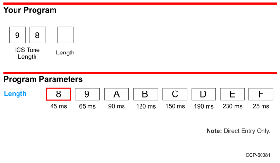
Tone Length (Milliseconds)
The Tone Length parameter sets the length of the tone for the ICS. By default, the tone length is set to 45 ms.
Programming Tags
Programming Mode

Save and Reset

Hex 0

Hex 1

Hex 2

Hex 3

Hex 4

Hex 5

Hex 6

Hex 7

Hex 8

Hex 9

Hex A

Hex B

Hex C

Hex D

Hex E

Hex F