Using Strain Relief Bracket
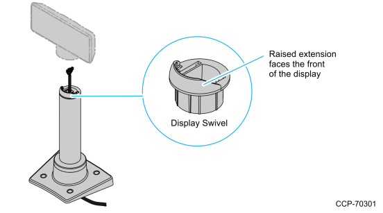
1.Route the display end of the Interface Cable through the Table–Top Mount, the Display Post, the Display Swivel, and the Swivel Bracket.
Note: The Strain Relief Bracket may be installed later.

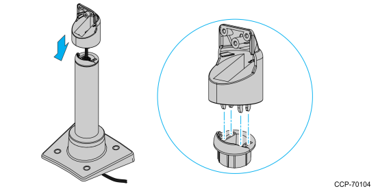
2.Assemble the post components.
Note: The raised extension of the Display Swivel is facing the front of the unit, which permits the Display to be tilted towards the back.
3.Attach the Swivel Bracket to the Display Swivel.
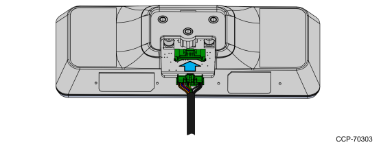
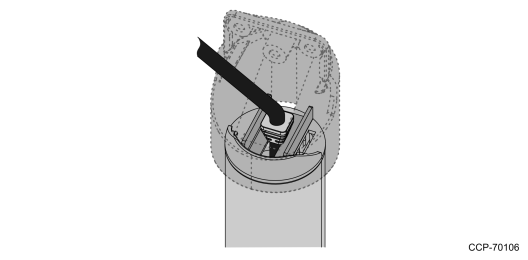
4.Connect the Interface Cable to the Display Module connector until the latch is engaged. Ensure that the latch is properly engaged by gently tugging on the cable.
5977–1000
5977–2000
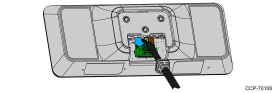
5.Attach the Strain Relief Bracket.
a.Attach the Strain Relief Bracket to the cable, right below the Cable Overmold.
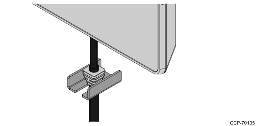
b.Carefully pull the cable down so the Strain Relief Bracket fits in the middle of the Swivel Bracket and rests on top of the Display Swivel.
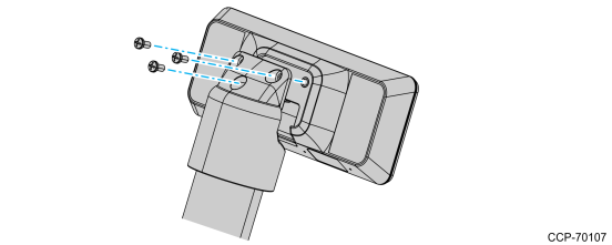
6.Attach the display to the Swivel Bracket by using the three M4x8 screws.
Note: Ensure that no cables are pinched.
7.Connect the terminal end of the Display Cable to the host terminal.
•RS–232 Interface (Powered)
Connect the I/F cable to a powered RS–232 connector on the terminal.
Configure the terminal serial port as follows:
9600 baud, 8 data bits, 1 start bit, 1 stop bit, No parity
•USB Interface (Powered)
Connect the I/F cable to a powered 12V USB + Power connector on the terminal.
•USB Interface (Non–Powered)
Connect the I/F cable to a non–powered USB connector on the terminal. Connect a Power Brick to the I/F cable and an AC outlet.