Retail Display Commands
The following table describes the Retail Display commands supported:
|
Command |
Function |
|---|---|
|
1B 01 |
Reset Display |
|
1B 02 |
Erase Display |
|
1B 03 |
Invalid Command |
|
1B 04 |
Set Diagnostic State On |
|
1B 05 |
Set Display State On |
|
1B 06 |
Set Low Power State On (Default) |
|
1B 07 |
Enable Cursor |
|
1B 08 |
Disable Cursor (Default) |
|
1B 09 |
Set Screen Save Blank (Default) |
|
1B 0A |
Set Screen Save Walk |
|
1B 0B |
Turn On Screen Save |
|
1B 0C |
Disable Screen Save Feature |
|
1B 0D |
Enable Character Blink |
|
1B 0E |
Disable Character Blink (Default) |
|
1B 0F |
Move Cursor Left |
|
1B 10 |
Move Cursor Right |
|
1B 11 |
Move Cursor Up |
|
1B 12 |
Move Cursor Down |
|
1B 13 |
Set Cursor Position |
|
1B 14 |
Query All Character Set Code Name |
|
1B 17 |
Brightness Adjustment (Default = 2) |
|
1B 18 |
Read Display ID |
|
1B 19 |
Read Display ID String |
|
1B 1B |
Display ESC Character |
|
1B 20 |
Select Character Set 1 (Default) |
|
1B 21 |
Select Character Set 2 |
|
1B 22 |
Select Character Set 3 |
|
1B 23 |
Select Character Set 4 (External Memory required) |
|
1B 24 |
Select Character Set 5 (External Memory required) |
|
1B 25 |
Select Character Set 6 (External Memory required) |
|
1B 26 |
Select Character Set 7 (External Memory required) |
|
1B 27 |
Select Character Set 8 (External Memory required) |
|
1B 28 |
Select Character Set 9 (External Memory required) |
|
1B 29 |
Select Character Set 10 (External Memory required) |
|
1B 2A |
Select Character Set 11 (External Memory required) |
|
1B 2B |
Select Character Set 12 (External Memory required) |
|
1B 2C |
Select Character Set 13 (External Memory required) |
|
1B 2D |
Select Character Set 14 (External Memory required) |
|
1B 2E |
Select Character Set 15 (External Memory required) |
|
1B 2F |
Select Character Set 16 (External Memory required) |
|
1B 30 |
Select Character Set 17 (External Memory required) |
|
1B 31 |
Select Character Set 18 (External Memory required) |
|
1B 32 |
Select Character Set 19 (External Memory required) |
|
1B 33 |
Select Character Set 20 (External Memory required) |
Reset Display
|
Format |
1B 01 |
|
Returns |
xx yy zz |
|
xx=microcontroller status 00 — OK If failure occurs, the firmware performs a loop forever. |
|
|
yy=Flash status 00 — OK, present 01 — Not present FF — Failure |
|
|
zz=number (in hexadecimal) of character sets available in the Flash 00=10 |
Description
This command executes the power–down power–up diagnostic sequence. The communication lines (RTS for serial, BUSY for parallel) are placed in an exception condition (see the “Diagnostics” section). The microcontroller test consists of a sum–check test on the ROM and a write/read test on the RAM. A check–sum test is also performed on the FLASH that holds any user defined character sets. After executing the command, the three status bytes (see above) are sent to the host, the display screen is cleared, the cursor moves to the 0 position, communication line exception conditions are cleared, and all registers and variables are initialized. Note that the screen is cleared during this command. If a host needs previous data redisplayed, the host must resend the previous data after this command has completed. Since true bi–directional communications are not available for the parallel interface, a unique interface utilizing the Strobe line as a clock line and the Ack line as a data line is used.
Erase Display
|
Format |
1B 02 |
Description
This command clears all of the displayed characters by writing a space to each display position. A space is defined as character 0x20 of the current character set. The cursor moves to the 0 position.
Invalid Command
|
Format |
1B 03 |
Description
This is now an invalid command.
Set Diagnostic State
|
Format |
1B 04 |
Description
This state is exclusive from the On and Low Power states. This command causes the firmware to display the current NCR firmware part number of the device (for example, the current firmware part number for the device is 497–0408199) for five seconds and then step through each installed 256–character set (default and user defined) displaying one character at a time on all 40 display positions at a rate of about one character per second. Start with the currently selected character set and then display all of the characters from the other sets the same way. This continues until one of the other state commands is performed. Prior display data is saved and can be restored be sending the Turn On (state 3) command.
Set Display State On
|
Format |
1B 05 |
Description
This state is used for normal run–time conditions. This operation instructs the firmware to leave one of the other states and begin performing normal refresh operations. There may be a slight delay before the display reaches the specified brightness setting when exiting the Low Power State. This delay should not exceed 1 second from the time the command is received until the time the display reaches the specified brightness.
Highest priority is given to refresh operations and a lower priority is given to host communications. Host communications still work, but if a large amount of data is to be programmed in a very short time frame, it would work faster if the Blank State was programmed prior to the information transfer.
The Screen Save feature may be in force during the Display On state. This means that after about five minutes of no new display activity, the Screen Save feature could take over and cause the display to go blank or begin walking from right to left.
Set Low Power State On
|
Format |
1B 06 |
Description
This state is used to reduce Retail Display power consumption and extend the life of the Retail Display. Power is only removed from the display and the display is not refreshed. The Retail Display controller is still fully operational and continues to accept commands. This command causes the firmware to blank or turn off the Retail Display. Display data can be processed while the display is in the Low Power state, but it does not appear until the Low Power state is changed. The displayed character’s state is preserved so that upon leaving the Low Power State the display is restored. To leave the Low Power State, one of the other state commands must be received. This is the default state for the Retail Display after power–up.
Enable Cursor
|
Format |
1B 07 |
Description
This command causes a flashing cursor to be used whenever the Display On state is in force. When the cursor is enabled, the firmware shows a visible flashing cursor at the current cursor position. The flashing cursor should be visible for one second and then the character at the cursor position should be visible for one second. The effect is to alternate between the character and the cursor. The cursor is defined as character 095 of whatever character set is currently chosen. For the three supported character sets, the cursor is the bottom row of pixels turned on. For a user–defined character set, the cursor becomes whatever is defined as character 095 of the character set. When the cursor is enabled, it overwrites the character at the cursor position. If the cursor is disabled, the character at the cursor position is left visible.
Disable Cursor
|
Format |
1B 08 |
Description
This command causes the cursor to be turned off. This is the default state for the cursor after power–up. A disabled cursor does not overwrite a displayed character.
Set Screen Save Blank
|
Format |
1B 09 |
Description
This command is intended to preserve the life of the display hardware unit. The firmware maintains a five–minute timer that triggers this feature. The Screen Save feature can be disabled through a command from the host soft¬ware. When the feature is not disabled, two specific options exist. The Set Screen Save Blank operation causes the display to go blank when the timer expires. When the firmware receives the command code, the Screen Save mode is canceled and the five–minute timer is established. Screen Save Blank removes power from the Retail Display and does not refresh the display in the same manner as the Set Low Power On command. At power up, the timer is established at five minutes and Screen Save Blank is established as a default. The five minute timer is not reset by any invalid or incorrect command.
Set Screen Save Walk
|
Format |
1B 0A |
Description
This command causes the visible display to walk right to left when the Screen Save timer expires (five minutes). The characters on the 5976 display appear to walk across the corresponding display row from right to left. The two lines in the 2x20 Display walk in parallel completely off the left side of the dis¬play and then the two lines appear to come back from the right. If the display is space filled, then no effect is perceived even though the walking is taking place. The Screen Save Blank mode is the default mode after power up.
Turn on Screen Save feature
|
Format |
1B 0B |
Description
This command causes the one of the screen save functions (Set Screen Save Blank or Set Screen Save Walk) to activate immediately rather than waiting for the screen save timer to expire. If the Disable Screen Save Option command is in effect when this command is issued, it is canceled and the screen saver is enabled and activated immediately.
Disable Screen Save option
|
Format |
1B 0C |
Description
The firmware ceases to keep time for the screen save activity from the host software and the display neither goes blank nor begins to walk due to inactivity from the host. This command can be canceled by the Turn on Screen Save, Set Screen Save Blank, and Set Screen Save Walk commands.
Enable Character Blink
|
Format |
1B 0D |
Description
The blink attribute is the only modifier which is supported for the display character positions. The attribute itself is not necessarily programmed with each new character code. Rather, each time a new character is received, the current setting of the character blink operator is adopted as the working attribute for the new character. If a new character is received while character blink is enabled, the new character blinks. This makes it possible to have a display with both blinking and non–blinking characters. The blink period is one second on and one second off. All characters that are blink enabled, blink at the same time. The only way to cause an existing character to start or stop blinking is to set up the character blink operator, locate the cursor to the correct character, and resend the individual character code.
Disable Character Blink
|
Format |
1B 0E |
Description
This command counteracts the Enable Character Blink. The firmware implements all new character codes with an on and holding character presentation. On power up, the character blink modifier is defaulted to disabled.
Move Cursor Left
|
Format |
1B 0F |
Description
This moves the cursor one position to the left. When the cursor is at the left end of the upper line, it moves to the right end of the lower line. When the cursor is at the left end of the lower line, it moves to the right end of the upper line. The cursor location always indicates the position of the next character to be displayed, whether the cursor is enabled and blinking or not. After each character is displayed, the firmware performs a logical Move Cursor Right command.
Move Cursor Right
|
Format |
1B 10 |
Description
This command moves the cursor one position to the right. When the cursor is at the right end of the upper line, it moves to the left end of the lower line. When the cursor is at the right end of the lower line, it moves to the left end of the upper line. The cursor location always indicates the position of the next character to be displayed, whether the cursor is enabled and blinking or not. After each character is displayed, the firmware performs a logical Move Cursor Right command. When the cursor is at the right end of the lower line, it moves to the left end of the upper line and operates in an Overwrite Mode (i.e.: The next character sent to the display overwrites the character in the left end of the upper line).
Move Cursor Up
|
Format |
1B 11 |
Description
This command moves the cursor up one line. When the cursor is on the upper line, the cursor is moved to the same column on the lower line. The cursor location always indicates the position of the next character to be displayed, whether the cursor is enabled and blinking or not. After each character is displayed, the firmware performs a logical Move Cursor Right command.
Move Cursor Down
|
Format |
1B 12 |
Description
This command moves the cursor down one line. When the cursor is on the lower line, the cursor is moved to the same column on the upper line. The cursor location always indicates the position of the next character to be displayed, whether the cursor is enabled and blinking or not. After each character is displayed, the firmware performs a logical Move Cursor Right command.
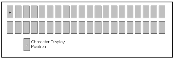
Move to Specified Position (or Set Cursor Position)
|
Format |
1B 13 nn |
|
Range |
00 ≤ nn ≤ 27 (Hex) |
Description
This command moves the cursor to the specified position. Position 0 is the upper leftmost position and position 27 is the lower rightmost position. Any value outside this range is discarded, the command is ignored, and the cursor is not moved. The cursor location always indicates the position of the next character to be displayed, whether the cursor is enabled and blinking or not. After each character is displayed, the firmware performs a logical Move Cursor Right command. The character positions are shown below.
Query All Character Set Code Name
|
Format |
1B 14 |
|
Returns |
All character set codename in HEX format padded by 0x2C |
Description
This command is a request for the Retail Display to return all the available character set codes stored in its memory. Maximum of 20 character set codes to be returned which are separated by comma (0x2C).
Brightness Adjustment (Default = 2)
|
Format |
1B 17 nn |
|
Range |
01 ≤ nn ≤ 05 (Hex) |
Description
This command adjusts the brightness of the entire display. Individual characters or display positions are not adjusted. On power up, the default brightness setting is
5 (100%).
Note: To change the brightness level, refer to Chapter 8, “Service Support Utility” for instructions.
|
nn |
Brightness |
|---|---|
|
01 |
20% |
|
02 |
40% |
|
03 |
60% |
|
04 |
80% |
|
05 |
100% |
Read Display ID Byte
|
Format |
1B 18 |
|
Returns |
0x8A |
Description
This command is a request for the Retail Display to return a identifier. The Retail Display returns one byte (0x8A) that identifies the Retail Display as a 2x20 with 7x9 dot matrix. Since true bi–directional communications are not available for the parallel interface, a unique interface utilizing the Strobe line as a clock line and the Ack line as a data line is used.
Read Display ID String
|
Format |
1B 19 |
|
Returns |
“NCR 5977, 497-0499797,V1.14.01,<S/N:(11 bytes)>” in Hex format Note: The quotation marks “” are not part of the string and are not returned. |
Description
This command is a request for the Retail Display to return an ASCII string with detailed product information. Since true bi–directional communications are not available for the parallel interface, a unique interface utilizing the Strobe line as a clock line and the Ack line as a data line is be used.
Display ESC Character
|
Format |
1B 1B |
Description
This command is a request for the ESC character to be displayed to the current cursor position.
Select Character Set n (Default = 1)
|
Format |
1B 20 – 1B 33 |
Description
This set of commands chooses one of the six supported internal character sets or, if an external character set is present, one of not less than 20 character sets.
•Character set 1 is defined as PC Code Page 858 (International).
•Character set 2 is defined as Katakana (Japanese).
• Character set 3 is defined as Cyrillic (Eastern European).
Note: The function where n is set to between 4 and 20 requires an External Memory.
Character sets 4 through 20 are only valid if extra character sets are present. Character set selection is dynamic. Host software can switch between character sets at any time. Switching between sets does not erase or change the display. This means characters from multiple character sets may be on a display. The default character set is number 1, PC Code Page 858 (International).