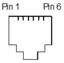
Cash Drawer Connector and Pin Assignments
The following illustration shows the pin out designation for the cash drawer connectors. The following table provides the pinout assignments for cash drawers one and two. The cash drawer connectors are located at the rear of the printer.

|
Pin Number |
Cash Drawer 1 Connector |
Cash Drawer 2 Connector (Optional) |
|---|---|---|
|
1 |
Frame Ground |
Frame Ground |
|
2 |
Drawer 1 Solenoid |
Drawer 2 Solenoid |
|
3 |
Drawer 1 & 2 Status Switch |
Drawer 2 Status Switch |
|
4 |
+24 Volts (to Solenoid +) |
+24 Volts (to Solenoid +) |
|
5 |
Drawer 2 Solenoid |
Drawer 2 Solenoid |
|
6 |
Ground (Status Switch Return) |
Ground (Status Switch Return) |
Note: For Cash Drawer 2, use the cash drawer Y-cable. For more information, refer to Ordering Other Supplies.