Connecting the Scanner to the Sensormatic Controller
Caution
To avoid damage to the controller, DO NOT reverse the order of connecting the Sensormatic cables, and DO NOT connect or disconnect the cables from the controller when the power is ON.
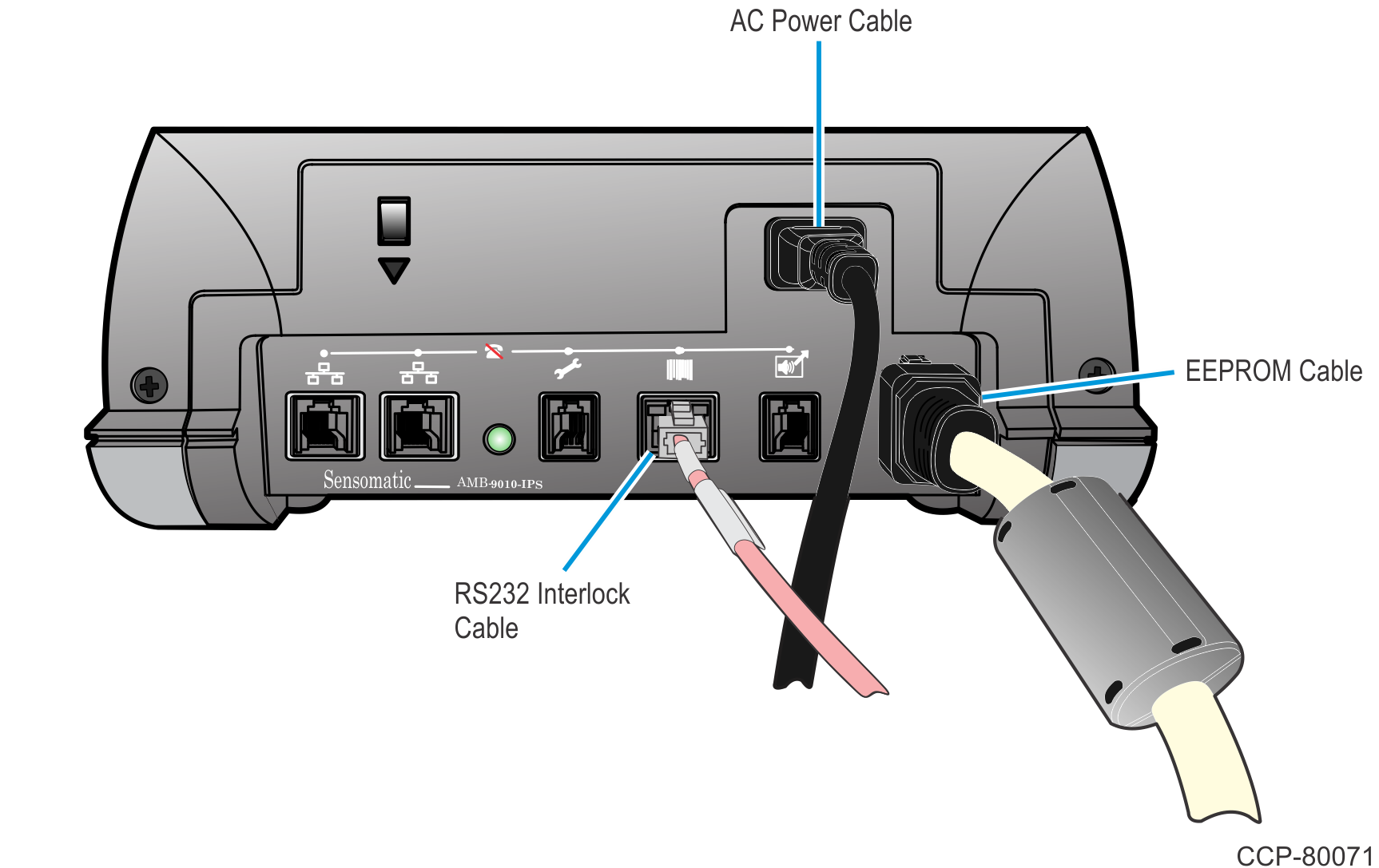
- Connect the Sensormatic Antenna EEPROM Cable to the EEPROM cable port on the Sensormatic Controller.
- Connect the Sensormatic RS-232 Interlock Cable to the scanner port on the Sensormatic Controller.
- Connect the Sensormatic AC Power Cable to the Sensormatic Controller.
- Connect the other end of the Sensormatic AC Power Cable to the unswitched AC outlet that has less than 0.5Vac between neutral and ground.Caution
The Sensormatic AC Power Cable must not be connected to the same power strip with the POS or SCO terminal.
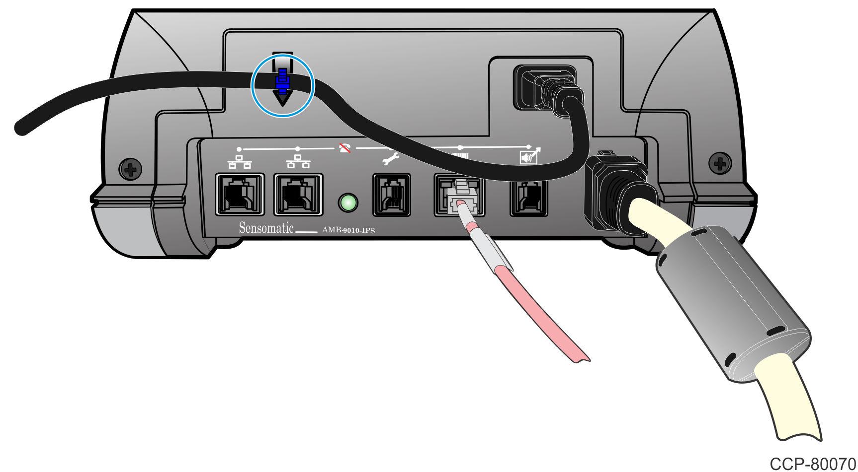
- Use a cable tie to secure the Sensormatic AC Power Cable to the back of the controller.
Note
The Status LED blinks green. While the controller auto-synchronizes, this LED can briefly flash amber. Auto-sync can take up to 10 seconds.
Caution
If the Status LED is solid red, stop the installation and return the controller to an authorized repair center.
Caution
When removing the controller for service, leave the coil EEPROM cable in place. The EEPROM maintains the system settings for the coil location and automatically updates the new controller.