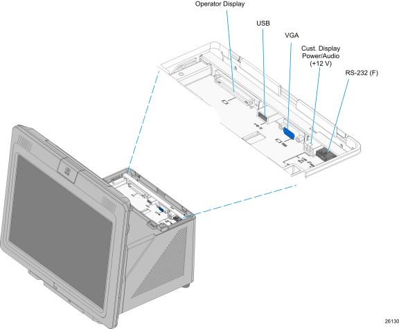
I/O Board
The I/O Board is used to provide external connections for the motherboard. It slides into position in the terminal below the motherboard.
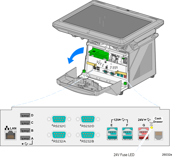
I/O Board Connectors
•Ethernet
•One 10/100/1000 MDI port
•USB
•Four High Speed Ports. Each port is capable of supplying 5 V at 0.5 A max. Self healing polyfuses are used to provide current protection.
•Two 12 V High Speed USB+Power ports. Each port is capable of supplying 12 V at 2.0 A max. Connected peripherals must not exceed this rating. Self healing polyfuses are used to provide current protection.
•One 24 V High Speed USB+Power ports. The port is capable of supplying 24 V at 0.5 A continuous and 3.0 A peak. A self-healing Poly-Fuse is used to provide current protection.
•Serial Ports (4)
•RS-232 ports with selectable power (+5 V, +12 V, or RI) on pin 9. (One RS 232 port is connected to the backplane and is available on the Backplane Board.)
Note: By default, Windows assigns COM 1-4 to the COM ports on the front of the terminal (labeled COM A-D). Additionally, there is a COM port on the back of the terminal, which is dedicated to integrated customer displays. Windows assigns COM6 to this port. Finally, there is an internal COM5, which is used by the Advanced Management Technology feature.
•Cash drawer Kickout port
•Support for two cash drawers on a single port
Additional peripheral connectors are located under the Customer Display.