Installing an NCR 5975/5976 Remote Customer Display
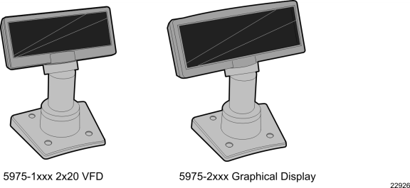
There are two models of the NCR 5975/5976 Remote Customer Displays:
•5976-1xxx - 2x20 VFD
•5975-2xxx - Graphical VFD
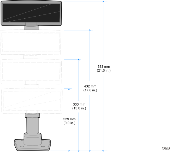
There are four different length posts available, in four inch increments.
1.Locate the Display Mount within 4 meters (13 ft.) of the host terminal.
2.Determine if the cable should be routed down through the mounting surface or if it should be run on top of the surface. Drill a hole if necessary.
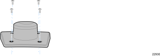
3.If you are installing with a post greater than 215 mm (8.5 in.) secure the Base Plate with screws (4) that are provided.
4.Connect the Interface Cable to the Display Module.
a.Remove the screws (2) from the Display Back.
b.Remove the Display Back.
c.Route the Interface Cable though the opening in the Display Back.
d.Connect the cable to the proper connector on the Display Module.
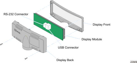
e.Reassemble the Display Assembly.
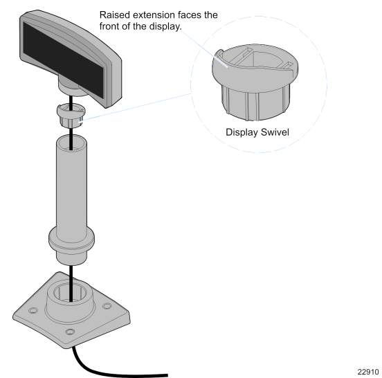
5.Route the Interface Cable through the Post and assemble the Post components.
6.Connect the Display Cable to the terminal, based on the type of interface you are using.
USB Interface (Powered)
Connect the I/F cable to a powered 12V Powered USB connector on the terminal.
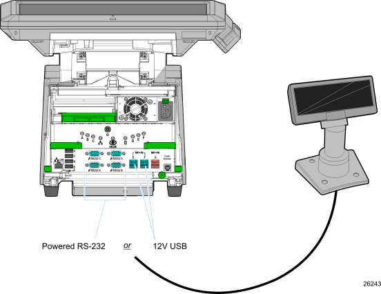
RS-232 Interface (Powered)
Connect the I/F cable to a powered RS-232 connector on the terminal.
Note: The factory settings for the COM ports are non-powered by default. To change a port to powered see the Circuit Boards chapter in the NCR RealPOS 72XRT Service Guide, B005-0000-2230.
Configure the terminal serial port as follows:
•9600 baud
•8 data bits
•1 start bit
•No parity
•1 stop bit
•Half-Duplex