Inspecting and Adjusting the Thickness Sensor
The Fujitsu F53 Note Dispenser contains an on-board diagnostic used to perform the thickness adjustment. The procedure for adjusting the thickness sensor consists of the following tasks:
1.Inspect the current thickness sensor value. See Inspecting the Thickness Sensor Value.
2.Adjust the thickness sensor to a setting within the valid range using the thickness gauge note. See Adjusting the Thickness Sensor.
3.After obtaining a thickness sensor value that is in range, remove the thickness gauge note from the unit. See Removing the Thickness Gauge Note
4.Run the dispense test to ensure correct operation.
Inspecting the Thickness Sensor Value
1.Disconnect the Note Dispenser power connector (J1) from the DC Hub.
2.Short the TRM2 Jumper on the Note Dispenser board by moving the jumper to cover both pins.
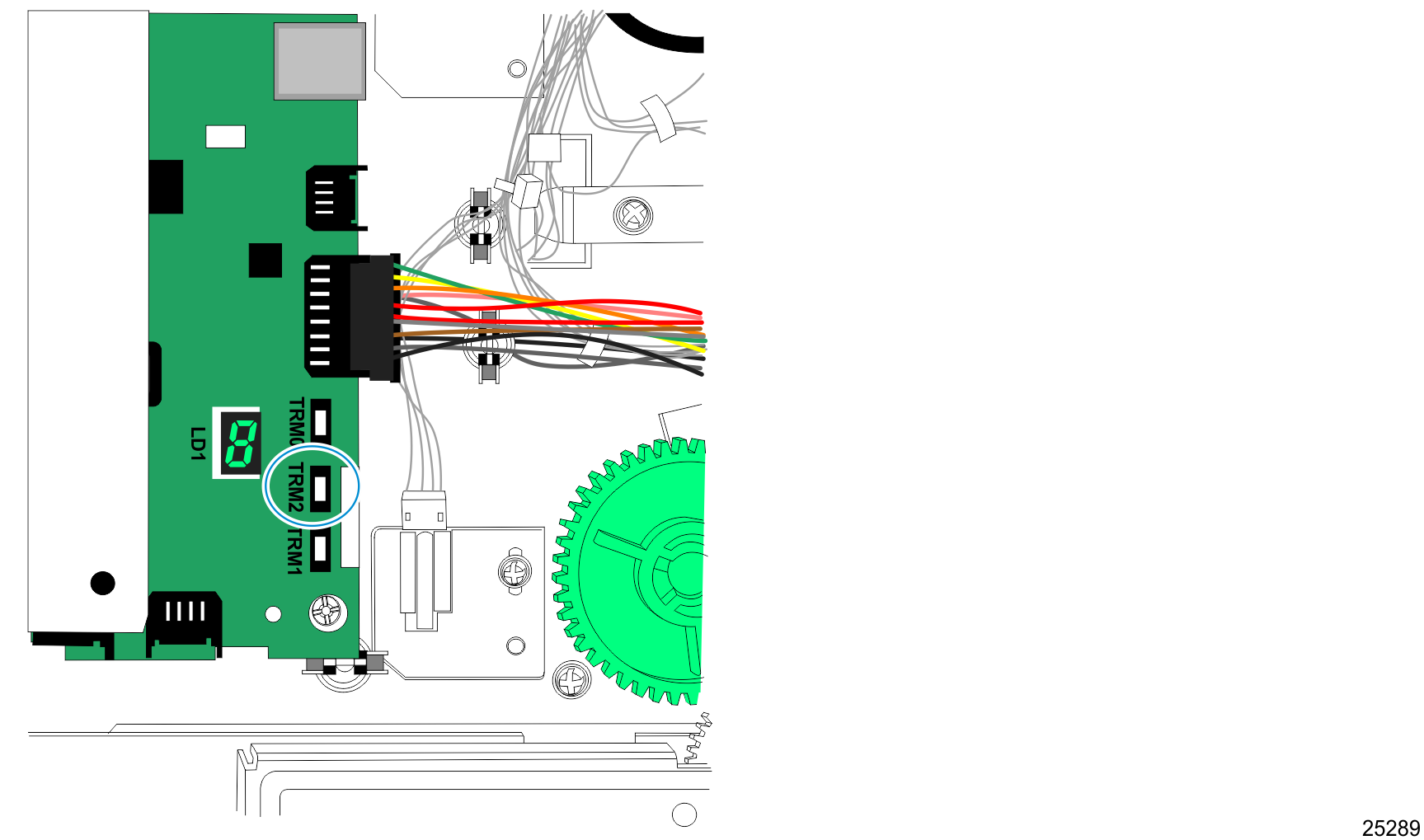
3.With the TRM2 shorted, power up the Note Dispenser by re connecting the Note Dispenser power cord to the DC hub. The LED display cycles from 0 through C and starts over. (For example, 0, 1, 2, 3, 4, 5, 6, 7, 8, 9, A, b, c.)
4.When the display reaches "A", pull off the jumper. RAS mode "A" displays the current value of the thickness adjustment. The thickness adjustment value is a hex value and should be in the range of E3 to Eb. If the value is out of the prescribed range, the sensor needs to be mechanically adjusted.
Note: The LED shows a lower case "b." A period is illuminated for the second digit as the LED cycles back and forth between digits. For example, BE would be shown as "b", "E." and EB would be shown as "E", "b."
Adjusting the Thickness Sensor
Tools required:
•JIS-P2 Screwdriver
•Small Flat Head Screwdriver
•Thickness standard gauge note for currency (NCR Part Number 497-0457292. Fujitsu part number D15L-0014-0157. Fujitsu Supply point PN USA0204711).
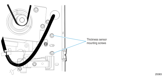
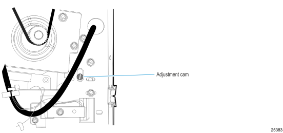
The thickness sensor can be adjusted through the following access holes.
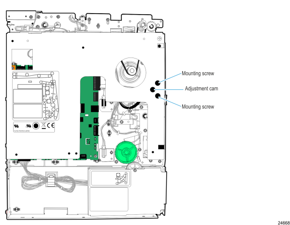
1.Loosen the two mounting screws slightly, approximately one-eight of a turn.
2.Turn the adjustment cam very slightly, to effect a change in the value of the sensor output. If the cam is turned too much, the sensor value can go higher than necessary.
Note: If the sensor value goes beyond FF in the range, the final steps of the procedure are not completed.
3.Once the adjustment is in range, tighten the two Phillips mounting screws to lock the bracket in position. (Note: The value needs to remain in the E3-EB range after tightening the screws.)
4.Put the jumper back on TRM2. The LED display starts counting again, cycling from 0 through C. When it reaches "B," pull the jumper off. The Note Dispenser unit's main motor cycles once and the display shows a dash.
Note: The LED shows a lower case "b."
5.Remove cassette #2 and insert the thickness gauge into the feed area.

6.Turn the green feed wheel to work the thickness gauge note up into the thickness sensor. Make sure the thickness gauge note moves at least one inch beyond the steel rollers.
7.With the thickness gauge note in place, the output should display the final value of 0-4.
•"If RAS B gives a good value, reinstall the jumper. The display changes to its counting after two seconds. When this occurs, the settings are complete.
•"If the output is higher than 4, or the dash does not change to a numeric value, the mechanical adjustment needs to be performed again. RAS B does not exit and a power reset is necessary to start RAS again. (Repeat the procedures for viewing and adjusting the thickness sensor value.)
Removing the Thickness Gauge Note
To remove the thickness gauge note:
1.Pull the jumper off when the display reaches 0. This step runs the continuous motor test and sends the thickness gauge note to the reject bin.
2.After the thickness gauge note is sent to the reject bin, put the jumper on one pin only.
3.Unplug the Note Dispenser power cable from the DC hub and then reconnect the power cable to power reset the Note Dispenser.
4.Run a Dispense Test to ensure correct operation.