Installing the Terminal
The NCR 7602 can be mounted on a countertop or placed free-standing, with the display remote.
This section explains how to install the NCR 7602 terminal to a RealPOS XL15 (5915) display using the Conversion Neck Assembly kit (7602-K300) and how to connect optional peripheral devices.
Note: The Conversion Neck Assembly kit (7602-K300) converts a RealPOS XR4 to RealPOS XR3 (7613). The RealPOS XL15 (5915) must be ordered for this kit.
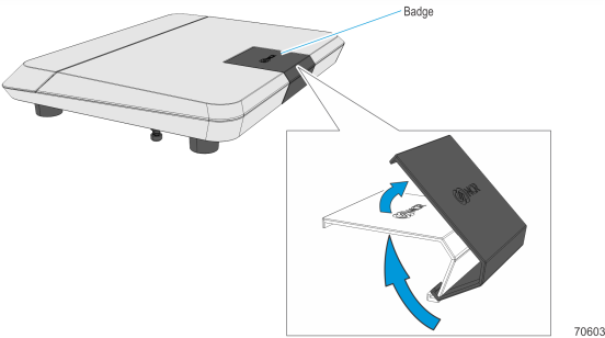
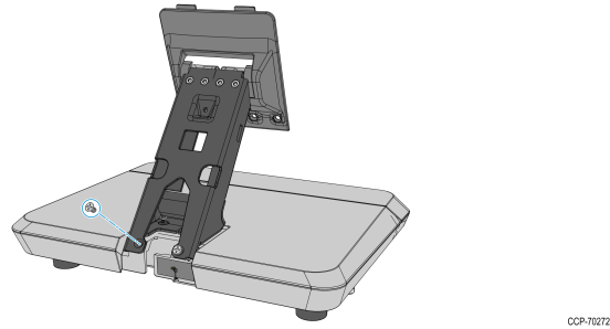
1.Push the Badge firmly from underneath the Base until it gets unhooked.
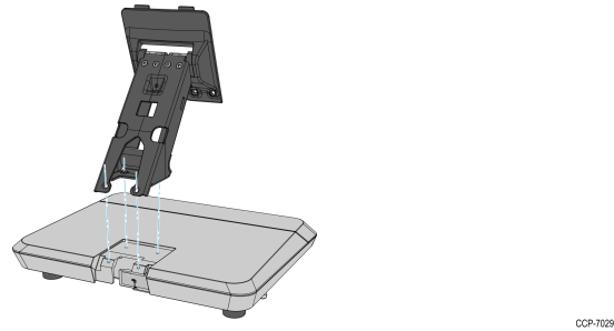
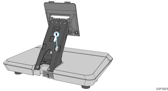
2.Mount and position the Neck Assembly on the Base.
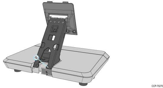
3.Mount and partially tighten a screw on one of the outside mounting holes.
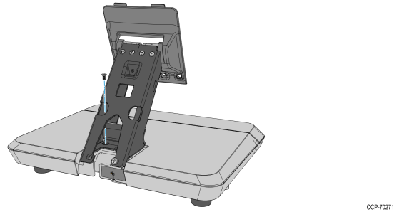
4.Mount and partially tighten a second screw on the inside mounting hole diagonally opposite to the mounted screw.
5.Mount and partially tighten the third screw on the second outer mounting hole.
6.Mount and fully tighten the fourth screw on the second inner mounting hole.
7.Fully tighten the three screws.
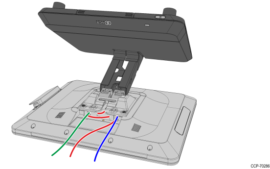
8.Connect the Display cables and route them according to the imprinted routing guide.
a.Connect and route the Audio Cable first. Route the cable looping around the cable guides as shown.
b.Connect the Display Power cable and route straight down over the audio cable.
c.Connect the Display Port cable and route straight down over the audio cable.

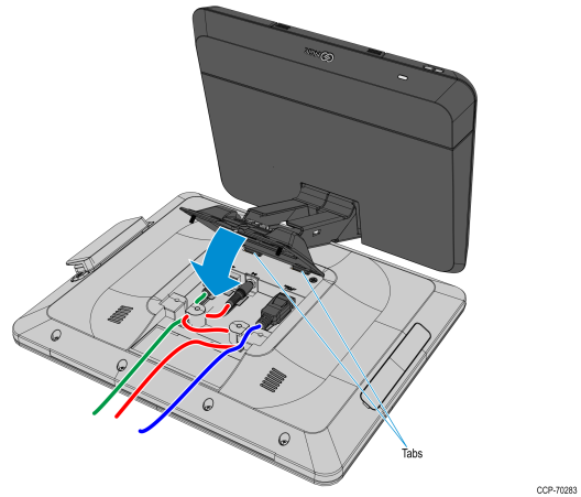
9.Mount the Neck and Base assembly on the Head assembly.
a.Insert the tabs on the Display Mounting Bracket to the slots on the rear of the Head Assembly and then slowly rotate the Neck and Base assembly downward.
b.Rotate the Base to position the Terminal in the orientation shown below.

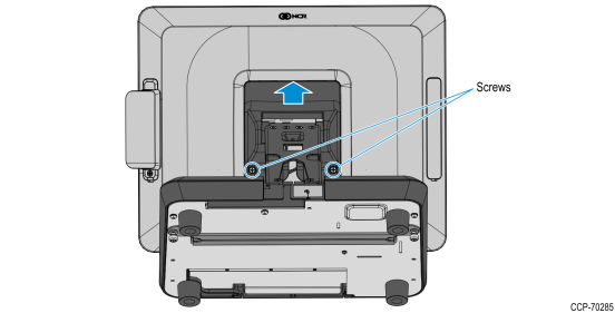
10.Slightly push the Neck and Base assembly forward to properly align its mounting holes with the Head. Secure the Base to the Head with screws (2).
11.Hold the display against the countertop and carefully rotate the Base to the position shown below.
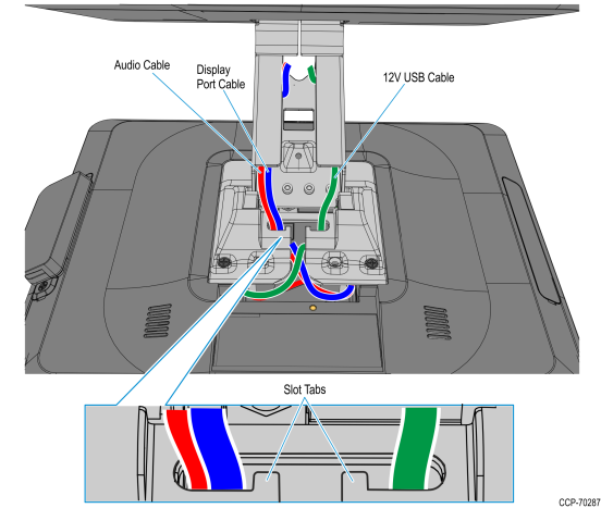
12.Route and secure the Display cables to the Mounting Bracket.
a.Route the Audio Cable to the left slot and make sure it is behind the tab in the slot.
b.Route the Display Port cable to the left slot and make sure it is behind the tab in the slot.
c.Route the USB cable to the right slot and make sure it is behind the tab in the slot.
13.Connect the USB cable to the connector at back of the base.

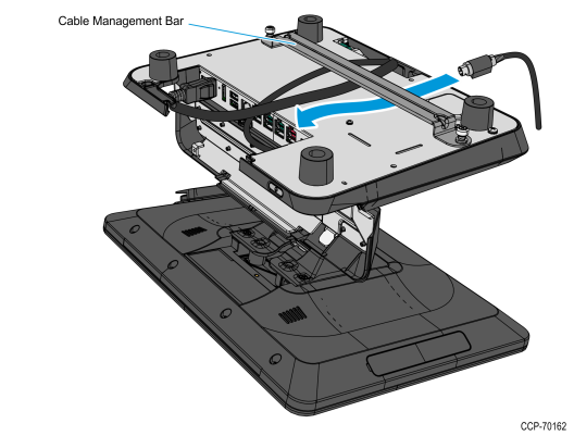
14.Route the Display Port and Audio cables towards the I/O panel at the front of the Base. If a cable management bar is installed, route the cables under the bar.
15.Open the I/O cover and connect the cables to the I/O Panel connectors.
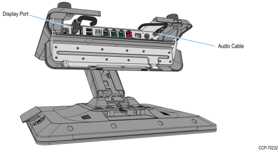
a.Connect the Audio Cable to the Audio Out connector on the I/O Panel.
b.Connect the Display Port cable to the Display Port A (Primary Display) connector on the I/O Panel.
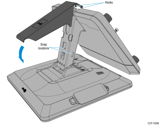
16.Mount the Neck Cover. Hook the Cover to the rear side of the Neck then rotate downward and press the Neck Cover until it latches on to the Neck.
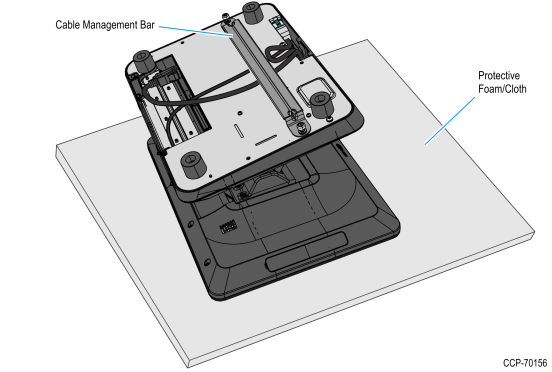
17.Lay the terminal face down on a flat surface.
Caution: Always use a soft material (cloth, foam) to protect the display screen when placing the terminal face down.
Note: The Cable Management Bar is an optional feature.
18.Open the IO Panel Cover. Press on the ribs on both sides, and then pivot the cover to open.
19.Connect the peripheral cables.
The available peripheral cable connectors on the IO panel are labeled in the illustration below.

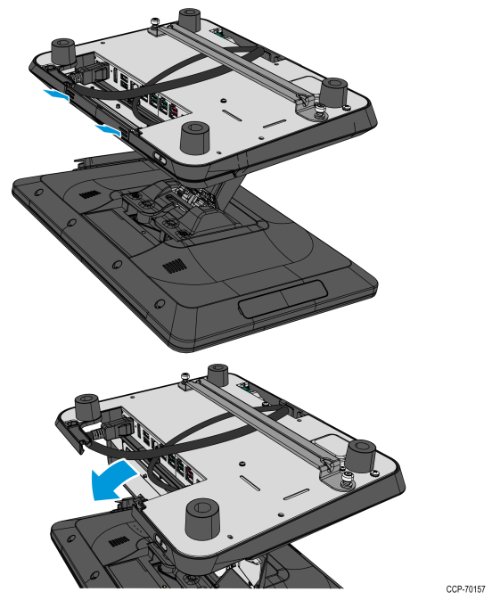
a.Route the cable from the back of the terminal towards the IO Panel.
Note: If a Cable Management Bar is present, route the cable under the Bar before connecting the cable to the IO Panel. The Bar may be removed by loosening the thumbscrews (2) that secure it to the bottom of the terminal.
b.Connect the peripheral cables to their assigned ports.
•For Transaction Printer, refer to Connecting the Transaction Printer
•For Cash Drawer, refer to Connecting the Cash Drawer
20.Connect the LAN Cable to the LAN connector on the terminal.
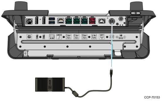
21.Connect the Power Adapter Cable to the DC Power connector on the terminal.
Caution: The NCR 7602 requires the NCR 24 V power supply that is shipped with the terminal. Use of other power bricks may cause damage to the unit.
22.Close the IO Panel Cover, and then carefully place the terminal upright on its feet.
Note: Make sure that all cables are correctly routed and are not pinched.
23.Remove the Touchscreen Protective Film from the Resistive or PCAP Touchscreen.
Note: The PCAP Touchscreen functions with the protective film in place, but for best results, remove the protective film.
24.Tilt the Display Head back to its original position.
25.Connect the AC Power Cord to the Power Supply and to an AC outlet.
Caution: Do not connect or disconnect the 24V Power Adapter Cable from the terminal with the AC Power Cord connected to an AC outlet.