Installing the Ingenico Lane 5000 and Axiohm TPOS 58mm Mount
To install the Ingenico Lane 5000 and Axiohm TPOS 58mm Mount to the Core Cabinet, follow these steps:
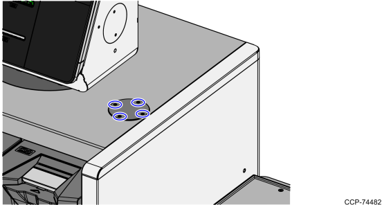
1.Remove four M4 flat head screws securing the PIN Pad Blank.
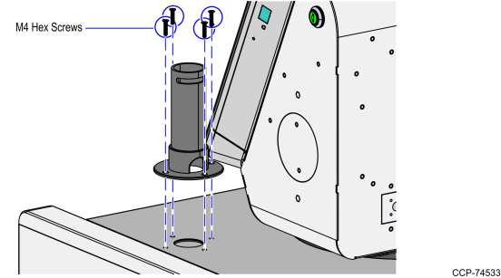
2.Secure the Mounting Pole on the Core Cabinet using four M4 Hex Screws. Ensure that the Pole holes are positioned as shown in the image below.
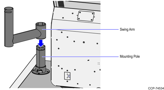
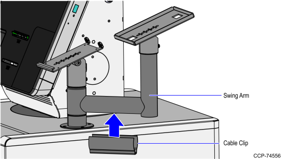
3.Attach the Swing Arm into the Mounting Pole as shown in the image below.
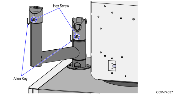
4.Using an allen key, loosen each screw on the SP2 Duratilt and SP2 NonTilting Top Pole Connection.
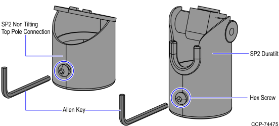
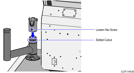
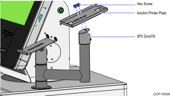
5.Attach the SP2 Duratilt to the Mounting Pole by aligning the hex screw with the slotted cutout as shown in the image below.
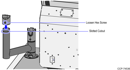
6.Attach the SP2 NonTilting Top Pole Connection to the Swing Arm by aligning the hex screw with the slotted cutout as shown in the image below.
7.Turn the SP2 Duratilt and SP2 Nontilting Top Pole Connection to the desired position and then tighten the corresponding hex screws using an allen key.
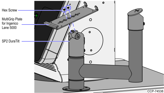
8.Install the MultiGrip Plate for Ingenico Lane-5000 to the SP2 Duratilt using two hex screws.
9.Install the Axiohm Printer Plate to the SP2 NonTilting Top Pole Connection using two hex screws.
10.Attach the Cable Clip into the Swing Arm as shown in the image below.
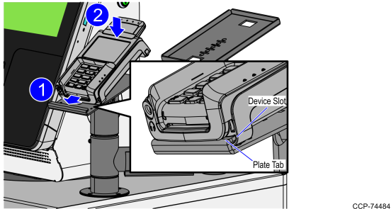
11.Place the Ingenico Lane 5000 into the MultiGrip Plate by inserting the Ingenico Lane 5000 device slot into the MultiGrip Plate tab as shown in the image below.
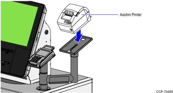
12.Place the Axiohm Printer into the Axiohm Printer Plate.
13.Route the Ground Strap cable. For more information, refer to Routing Ground Strap Cable.