Routing and Connecting Cables
Warning
Before connecting or disconnecting any cable, ensure that the NCR 7895 power is off.
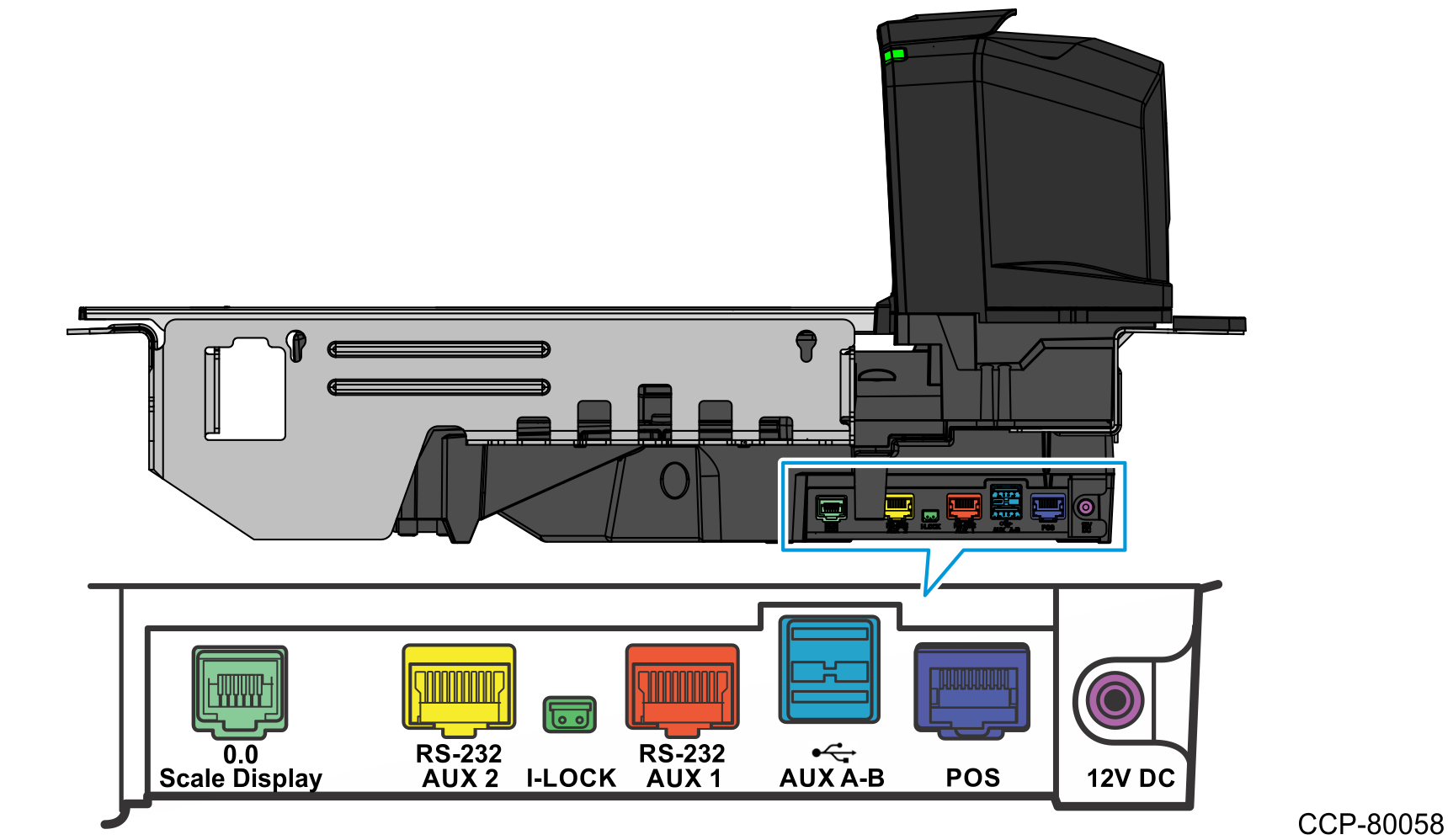
The NCR 7895 Scanner/Scale has external connectors located at the right side of the unit. When routing the power and interface cables for the NCR 7895, take note of the following:
- Do not route interface cables in close proximity to electrical motors or other sources of electromagnetic interference.
- When routing the Sensormatic Cables to the checkstand cutout, make sure that the Color Camera USB Cable is as far as possible from the Sensormatic Cables. This is to avoid signal interference between the Sensormatic device and the Color Camera Assembly.
- Drop the cables directly from their connectors on the scanner or route them along the side of the scanner to the back.
- If the NCR 7895 is powered by an external Power Supply, connect the Power Supply DC Cable to the NCR 7895 before connecting the Power Supply to the AC power source.
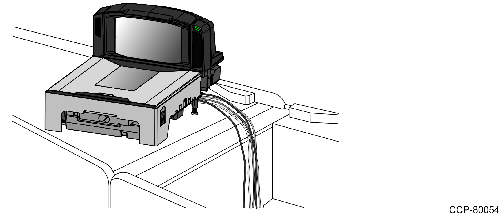
To route and connect cables to the NCR 7895, follow these steps:
- Position the unit so that the right side of the scanner is directly over the hole in the checkstand.
- Verify that all components have the correct interface cable.
- Connect the NCR 7895 to the POS terminal or to the external Power Supply, depending on the configuration.
- If the NCR 7895 is powered by an external Power Supply, connect the Power Supply DC Cable to the 12V DC port on the NCR 7895. Do not connect the Power Supply to the AC power source yet.
- If the NCR 7895 is powered by a host terminal, turn off the host terminal and connect the interface cable from the host terminal to the POS port of the NCR 7895.
- For NCR 7895 Color models, connect the Color Camera USB Cable to the USB 3.0 port of the POS terminal.
- f the configuration includes a Handheld Scanner with a USB interface cable, connect the Handheld Scanner to any of the two Aux A‑B USB 2.0 ports of the NCR 7895.Note
For more information, refer to Auxiliary Connections.
- If the configuration includes a Scale Display, connect the display cable to the Scale Display port of the NCR 7895.
- If the configuration includes an Electronic Article Surveillance (EAS) system, do either of the following:
- For Sensormatic Deactivation system, connect NCR 7895 to the Sensormatic Controller. For more information, refer to Connecting the Scanner to the Sensormatic Controller.
- For Checkpoint Deactivation system, connect the Checkpoint Controller cable to the I‑Lock port of the NCR 7895.