Installation Procedures
For back-to-back kiosk installation, both kiosks must be bolted to the floor using recommended anchors. Before installing the kiosk, ensure that the installation location is prepared and the mounting holes are drilled. The anchors or bolts are not shipped with the kiosk and must be obtained locally.
Note: For more information on mounting dimensions, bolt specifications, and anchor specifications, refer to NCR SelfServ™ XK22 (2246) Site Preparation Guide (BCC5‑0000‑5390).
Warning: Disconnect the AC power cord before disassembling the kiosk.
Note: The Power Strip is installed to the pedestal that is closer to the external AC power outlet and LAN port. For this procedure, Pedestal 1 refers to the pedestal with the Power Strip, while Pedestal 2 refers to the other pedestal.
To install the NCR XK22 Kiosk Pedestal Mount kiosks back to back, follow these steps:
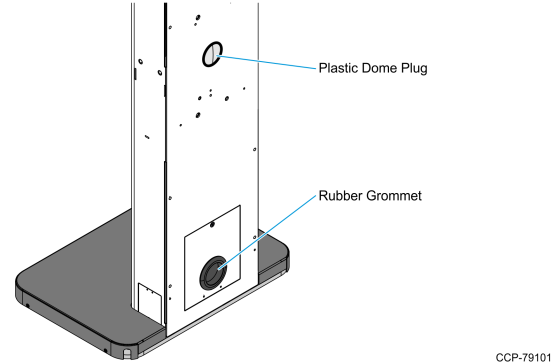
1.Remove the plastic dome plug and the rubber grommet that cover the cable access holes at the upper and lower back of the pedestals.
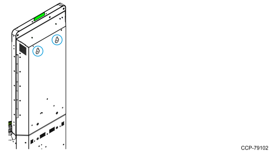
2.Using a flat–head screwdriver or a similar tool, remove the two knock–out features located on the upper module of the pedestals.
3.Position the two pedestals on their final installation locations.
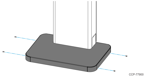
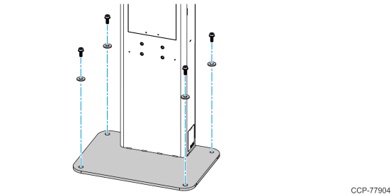
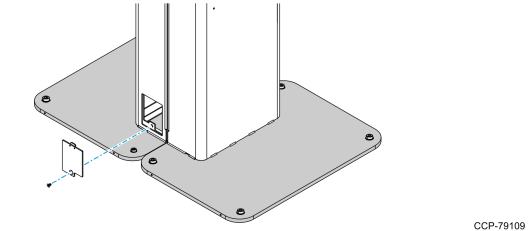
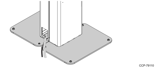
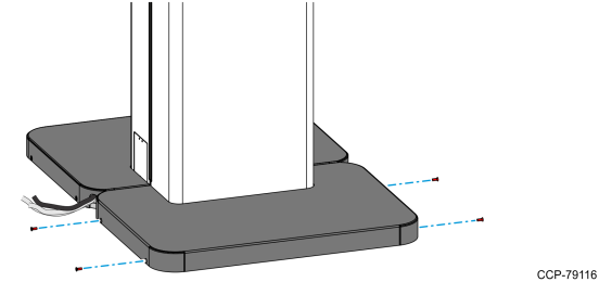
4.Remove the Base Cover from the pedestal base by removing the four screws indicated in the following image.
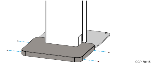
5.Align the four mounting holes on the pedestal base with the four mounting holes on the floor.
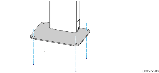
6.Secure the pedestal to the floor using four anchors and four washers.
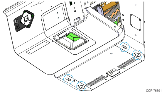
7.Using a flat–head screwdriver or a similar tool, remove the four knock–out features that cover the mounting holes on the bottom of the kiosk head.
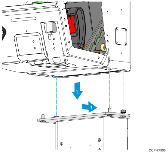
8.Install but do not tighten the two M8 Keps nuts onto the two rear mounting studs.
9.Position the kiosk head onto the studs on top of the pedestal adapter plate, and then slide the kiosk head toward the back.
10.While supporting the kiosk, open the Lower Module Door and do the following:
Note: For procedures on how to open the Lower Module Door, refer to Opening the Kiosk.
a.If the kiosk includes the Coupon Bin feature, remove the Coupon Bin from its mounting studs.
b.If the kiosk includes the Receipt Printer feature, remove the Receipt Printer from its mounting bracket. For more information, refer to Slightly slide the receipt printer upward to unhook it from its bracket, and then carefully remove the printer from its bracket..
c.If the kiosk includes the Checkpoint feature, remove the Checkpoint Controller, its power supply brick, and its mounting brackets from the kiosk. For more information, refer to Open the Upper Module Door and disconnect the Checkpoint Signal Cable connector from the CKPT connector on the I/O Adapter. Remove it from the p-loops along its route..
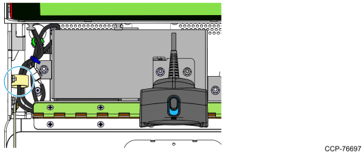
d.To access the mounting holes on the left side of the kiosk, remove the DC Power Cable from the p-loop indicated in the following image.
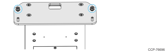
11.Install but do not tighten the two M8 Keps nuts on the two front studs.
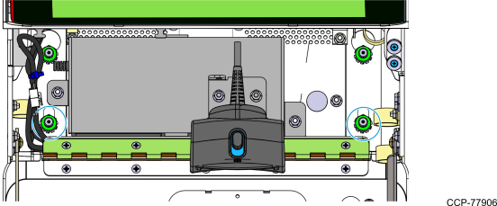
12.To fully secure the kiosk, tighten the four M8 Keps nuts.
Note: Do not fully tighten any nut on the first turn. Use a stepping method when tightening the nuts. Tighten each nut a little at a time to evenly install the kiosk to the pedestal.
13.Return the DC Power Cable to the p-loop indicated in the following image.

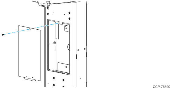
14.Remove the Front Access Door of the pedestals.
•Remove the screw that secures the Front Access Door to the pedestal.
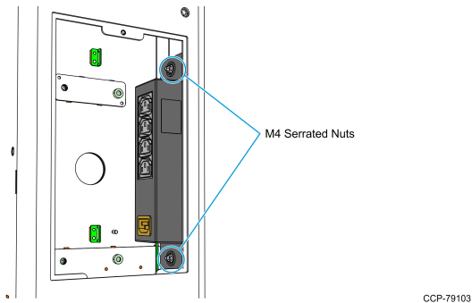
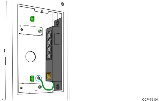
15.Install the Power Strip to Pedestal 1.
a.Mount the Power Strip to the studs on the right-hand wall of the pedestal and secure it using two M4 serrated nuts.
b.Attach the Power Strip ground cable to the stud indicated in the following image, and then secure it with an M4 serrated nut.
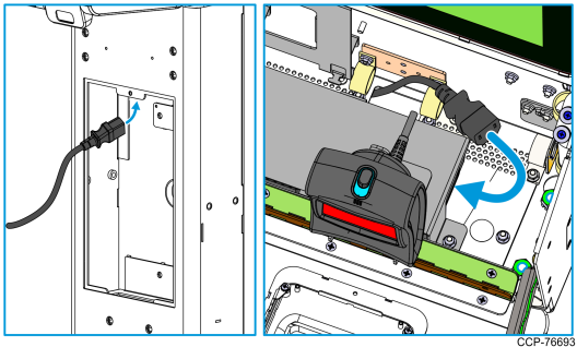
16.Connect and route the Kit AC Power Cables.
Note: Use the two AC Power Cables that comes with the kit. The AC Power Cable that comes with the original 2246 kiosk packaging will be used for connecting the Power Strip to the external AC power outlet.
•Insert one end of the Kit AC Power Cable into the Front Access Door and into the kiosk access hole, and then connect it to the power brick.
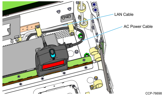
17.Route the LAN Cable through the access hole on the base of the kiosk, and then secure both LAN Cable and Kit AC Power Cable with p-loops along the route.
18.If the kiosk includes the Receipt Printer feature, re–install the Receipt Printer. For more information, refer to Connect the Power and USB cables to the rear side of the printer. Route the cables downward and secure them using the cable management features in the printer..
19.If the kiosk includes the Checkpoint feature, re–install the Checkpoint Controller, its power supply brick, and its mounting brackets. For more information, refer to Install the Checkpoint mounting bracket on the right inner side of the lower module and secure it with the two hex nuts..
20.If the kiosk includes the Coupon Bin feature, re–install the Coupon Bin on its mounting studs.
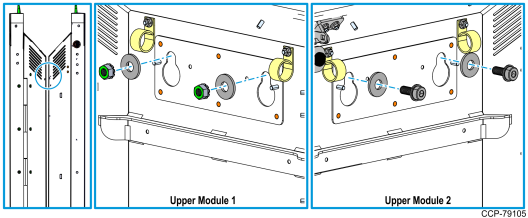
21.Close the gap between the two kiosks.
a.Open the Upper Module Door. For more information, refer to Opening the Kiosk.
b.Install the two M8 screws, two M8 nuts, and four washers through the holes on the upper module of the kiosks.
22.Route and secure the Pedestal 2 cables going to Pedestal 1.
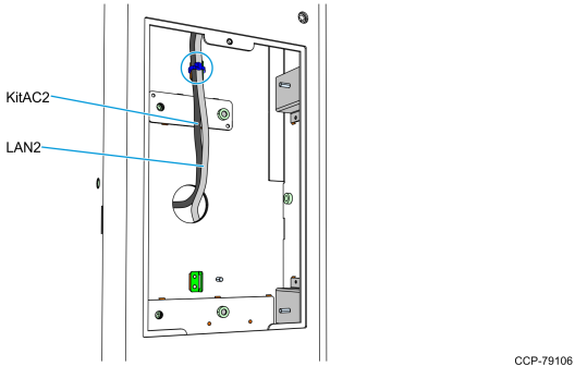
a.Insert the Kit AC Power Cable (KitAC2) and the LAN Cable (LAN2) through the upper back access hole.
b.Use a cable tie to secure the cables to the cable management bracket indicated in the following image.
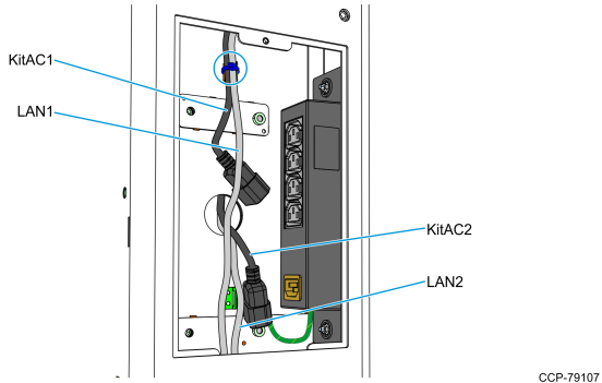
23.Secure the Pedestal 1 cables.
•Use a cable tie to secure the Kit AC Power Cable (KitAC1) and LAN Cable (LAN1) to the cable management bracket indicated in the following image.
24.Connect the following cables to the Power Strip.
Note: Power Strip AC Power Cable (PowStripAC) is the AC Power Cable that comes with the original 2246 kiosk packaging.
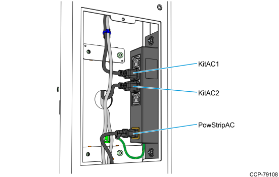
25.Use a cable tie to secure the LAN1, LAN2, and PowStripAC cables to the cable management bracket indicated in the following image.

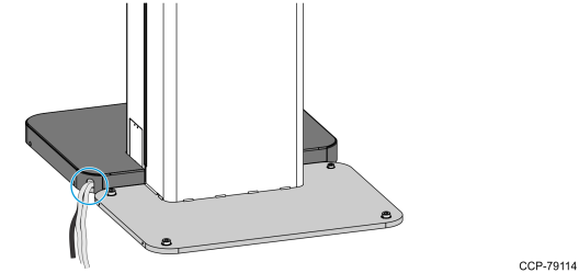
26.Route the LAN1, LAN2, and PowStripAC cables out of the pedestal, through the Side Access Door of Pedestal 1.
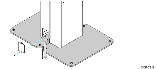
a.Remove the Side Access Door of the pedestal by removing the screw that secures it to the pedestal.
b.Route the LAN1, LAN2, and PowStripAC cables out of the pedestal. Verify that the cables are long enough to reach their external connection ports.
Caution: Do not plug the PowStripAC cable to the power source yet.
c.Re–install the Side Access Door to the pedestal and secure it with a screw.
Caution: Ensure that the cables are not pinched.
27.Re–install the Base Cover on Pedestal 1.
a. Position the Base Cover on top of the pedestal base, making sure to route the cables through the cable access hole of the Base Cover.
b.Secure the Base Cover with four screws.
28.Re–install the Base Cover of Pedestal 2 and secure with four screws.
29.Re–install the Front Access Door to the pedestals and secure it with a screw.