Installing the Tri-Light/Lane Light with IP Camera Assembly
To install the Tri-Light/Lane Light with IP Camera Assembly, follow these steps:
Note
Ensure that the NCR Customer Helpdesk is informed when the Tri-Light/Lane Light with IP Camera is installed in the store.
- Remove the existing Tri-Light/Lane Light Assembly, if necessary. For more information, refer to Removing the Tri-Light/Lane Light (R6).
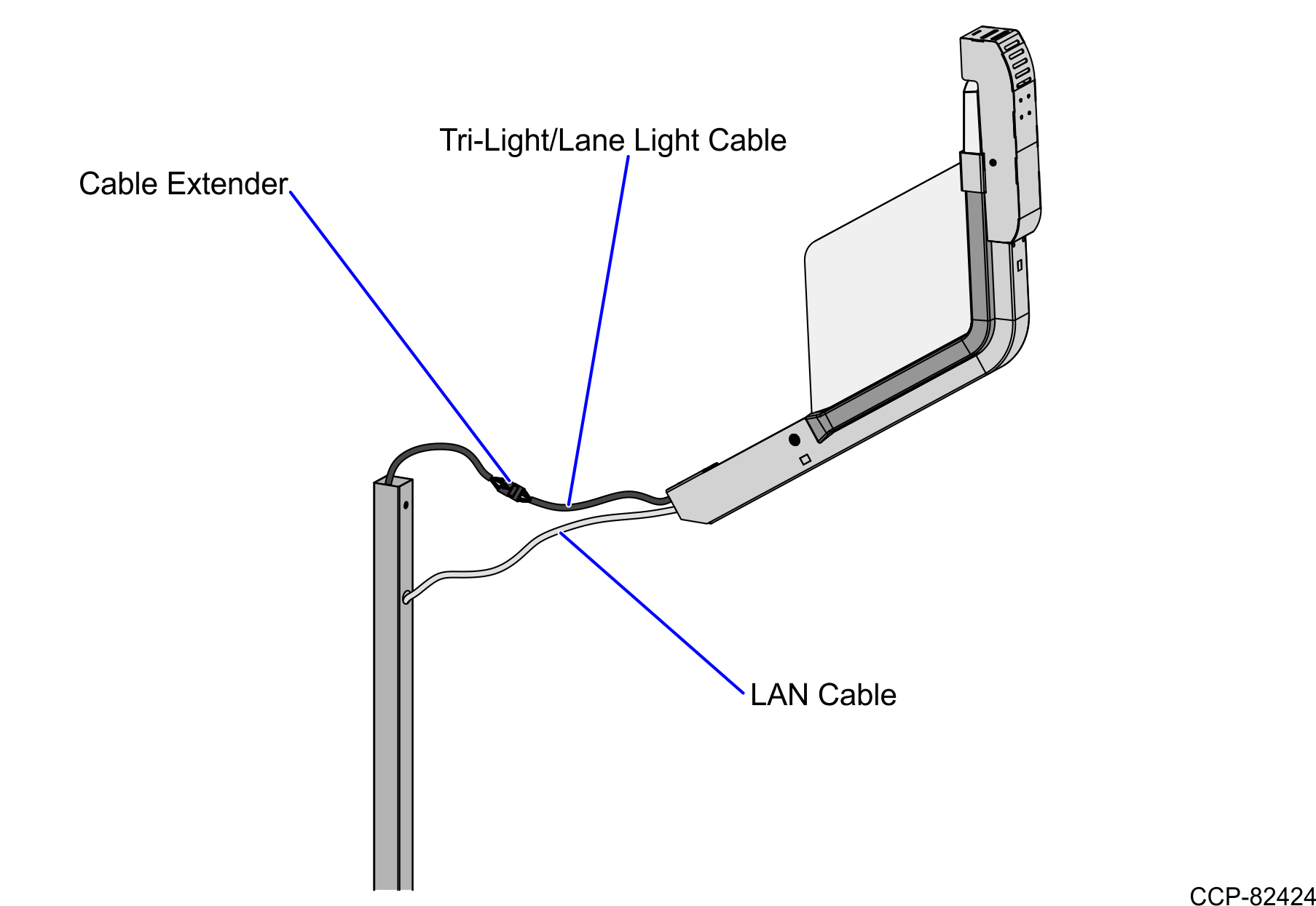
- Route the LAN Cable into the Tri-Light/Lane Light Pole.
- Connect the Tri-Light/Lane Light Cable to the cable extender.
- Orient the Tri-Light/Lane Light Assembly so that the Lane Light faces the front of the unit.
- Insert the Tri-Light/Lane Light Assembly into the Tri-Light/Lane Light Pole. Ensure that the pole holes are aligned.Note
Ensure that the LAN Cable and the Tri-Light/Lane Light Cable do not intertwine when installing the Tri-Light/Lane Light assembly to the Tri-Light/Lane Light Pole.
- Route and connect the Tri-Light/Lane Light and LAN cables to the corresponding port destinations:Note
For more information on routing cables, refer to Routing the CablesRouting the Cables: 7360 R6-C Full Function (Fixed)Routing the Cables: 7360 R6-C (Card Only)Routing the Cables: 7360 R6-C Full Function (Convertible).
Tri–Light Destination Connection (Location) Tri-Light/Lane Light cable extender I/O Box (Tri–Light/Lane Light port) Ethernet (LAN) cable extender PoE Switch NoteThe Camera should use an 802.3at (PoE+) compatible switch/injector. The Ethernet (LAN) Cable must be a Shielded Twitsted Pair (STP).
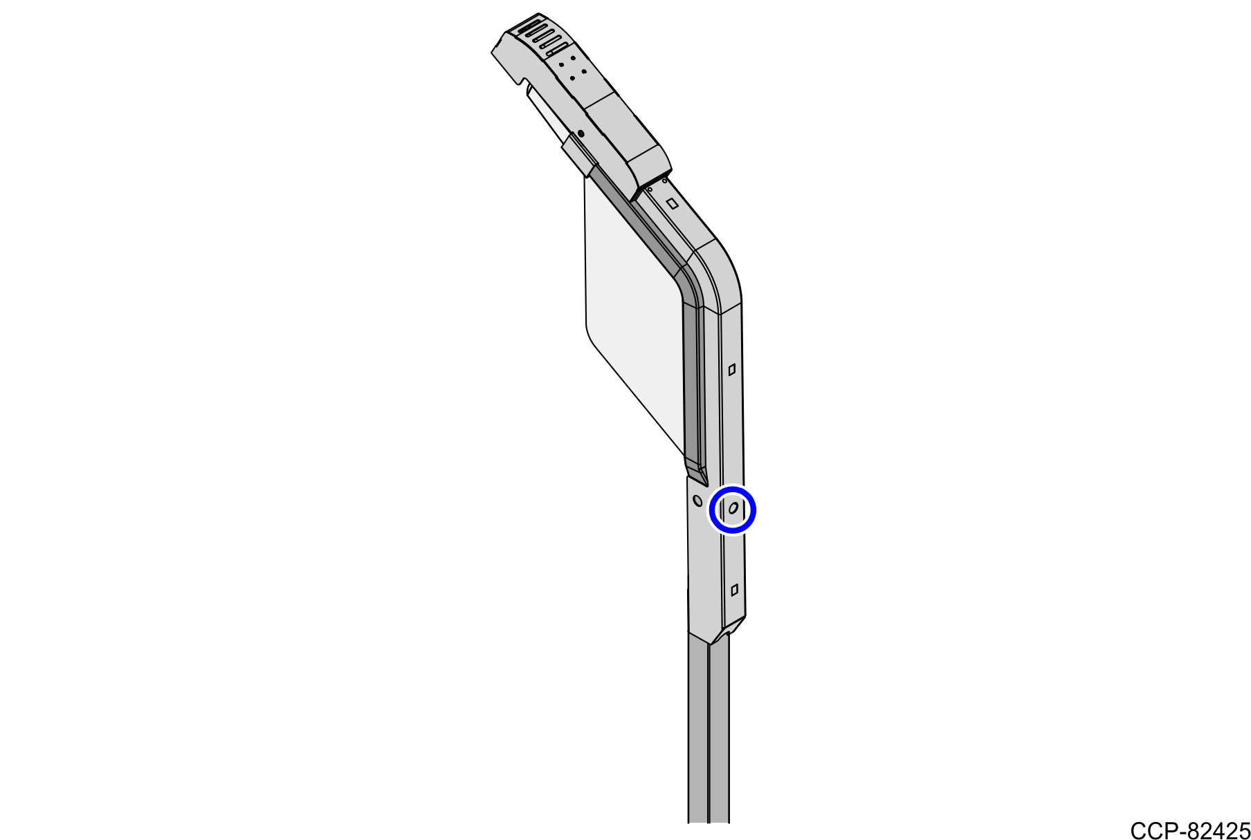
- Secure the Tri-Light/Lane Light assembly to the pole using one (1) screw.
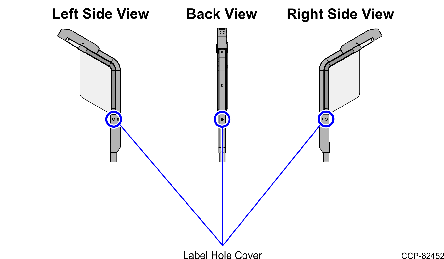
- Attach three (3) Label-Hole Covers to the holes on the Tri-Light/Lane Light, as shown in the image below.